Wide band lambda probe having improved starting behaviour

a lambda probe and wide band technology, applied in the direction of electrical control, instruments, material electrochemical variables, etc., can solve the problems of serious interference with regulation, slow increase of the nernst voltage from 0v to 450 mv, etc., to achieve avoid complicated suppression of the sensor output signal or a switch-off of the pump voltage, improve the starting performance, and avoid the effect of high amplification

Inactive Publication Date: 2006-10-03
ROBERT BOSCH GMBH
View PDF10 Cites 12 Cited by
  • Summary
  • Abstract
  • Description
  • Claims
  • Application Information

AI Technical Summary

Benefits of technology

[0009]Consequently, the present invention is based on the objective of indicating a method of the type described in the introduction as well as a control device, which avoid a previously described disruption of the lambda control during the start-up phase of the engine or during the cold phase of the broadband sensor.
[0011]Accordingly, the present invention allows the operation of a broadband lambda sensor that has better starting performance than the related art. For one, it avoids all early pump currents that are caused only by the false Nernst signal. Nevertheless, true concentration deviations are rapidly corrected as a result of the high amplification in the evaluation circuit provided in these types of sensors. Furthermore, complicated suppressions of the sensor output signal or a switching-off of the pump voltage is avoided.
[0012]In contrast to the pilot control provided in lambda=1 jump sensors, the extreme reaction of the sensor caused by the mentioned high amplification is effectively avoided by high pump voltages. Furthermore, the influence of the pumped reference as “rich” pilot control is reduced.

Problems solved by technology

It is thus disadvantageous in these sensors that, during the start-up of the engine or the sensor, the Nernst voltage increases only slowly from 0V to 450 mV even if the exhaust gas is at lambda=1 the entire time.
Thus, the output signal exhibits an overswinger in the lean direction, which seriously interferes with the regulation.

Method used


Image

  • Wide band lambda probe having improved starting behaviour
  • Wide band lambda probe having improved starting behaviour
  • Wide band lambda probe having improved starting behaviour

Examples


Embodiment Construction

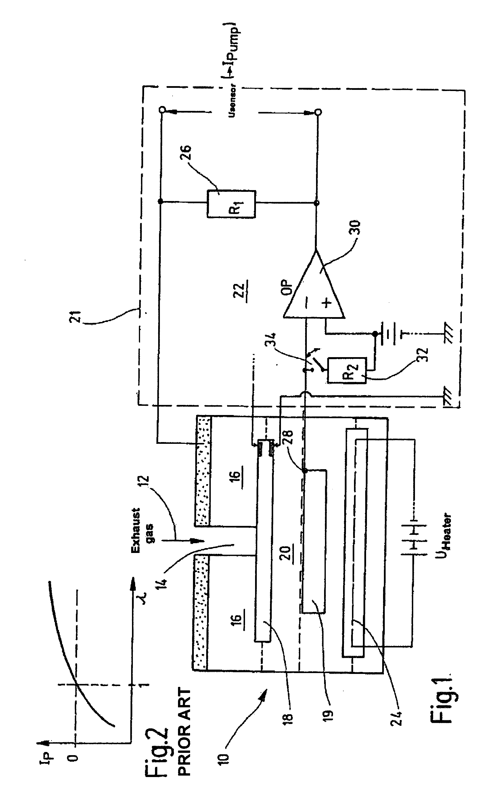
[0020]In the broadband lambda sensor 10 shown in FIG. 1, exhaust gas 12 reaches the actual measuring chamber 18 of a Nernst cell 20 through a small orifice 14 in a pump cell 16, the so-called “diffusion gap”, which acts as diffusion barrier. Adjacent to Nernst cell 20 is a reference gas chamber 19 containing an oxygen reference gas. Measuring chamber 18 is always set to a stoichiometric air-fuel ratio. An evaluation and control circuit 22 located in a control device 21 or similar device regulates a pump voltage U_Pump present at pump cell 16 in such a way that the composition of the gas in measuring chamber 18 remains constant at lambda=1. With lean exhaust gas 12, pump cell 16 pumps oxygen from measuring chamber 18 to the outside. On the other hand, when exhaust gas 12 is rich, the oxygen of exhaust gas 12 from the environment is pumped into measuring chamber 18, thereby reversing the direction of electric pump current I_Pump. The pump current is proportional to the oxygen concentr...


PUM

PropertyMeasurementUnit
voltageaaaaaaaaaa
sensor voltageaaaaaaaaaa
operating temperatureaaaaaaaaaa

Abstract

In a method and a control device for operating a broadband lambda sensor, the oxygen concentration of an exhaust gas is determined based on a comparison of a Nernst voltage with a reference voltage having a nominal value; a pump current is injected into a cavity of a pump cell if a deviation is present, an electric voltage present at the pump cell being regulated in such a manner that lambda=1 prevails in the cavity, the pump current being a measure for the value of lambda in the exhaust gas; and, in order to avoid control interference in the start phase of the engine or in the cold phase of the sensor, the Nernst voltage is maintained close to the reference voltage, using a pilot control, until the Nernst voltage is an actual measure for the oxygen concentration in the cavity of the pump cell.

Description

RELATED APPLICATIONS[0001]This application claims priority of and is a U.S. national phase application of PCT / DE02 / 02959, filed Aug. 13, 2002, and claims priority to DE 101 47 390.7, filed in Germany on Sep. 26, 2001.BACKGROUND INFORMATION[0002]A lambda closed-loop control in conjunction with a catalytic converter is currently the most effective exhaust-gas treatment method for the spark-ignition engine. Only in interaction with currently available ignition and injection systems is it possible to achieve very low emission values. Especially effective is the use of a three-way catalytic converter, or selective catalytic converter. This type of catalytic converter is able to break down more than 98% of hydrocarbons, carbon monoxides and nitrogen oxides provided the engine is operated within a range of approximately 1% around the stoichiometric air-fuel ratio at lambda=1. In this context, lambda specifies the degree to which the actually present air-fuel mixture deviates from the value...

Claims


Application Information

Patent Timeline
Patent Type & Authority Patents(United States)
IPC IPC(8): G01N27/00G01N27/419F02DF02D41/06F02D41/14G01N27/26G06F19/00
CPCF02D41/1456G01N27/4065
Inventor STRASSNER, WALTERDIEHL, LOTHARANDORFER, ANDREAS
Owner ROBERT BOSCH GMBH
Why Eureka
Try Eureka