
Apparatus and method for thermal plasma treatment of solid waste

A technology of solid waste and thermal plasma, applied in the direction of solid waste removal, etc., can solve the problems of short life, full utilization of unfavorable energy, large amount of working gas, etc., and achieve the effect of low cost

Inactive Publication Date: 2012-02-01
安徽中科华炬环保科技有限公司
View PDF4 Cites 2 Cited by
  • Summary
  • Abstract
  • Description
  • Claims
  • Application Information

AI Technical Summary

Problems solved by technology

[0004] All of the systems mentioned above have some significant drawbacks, for example, the waste does not have sufficient mixing, melting, and residence time at high temperatures, and does not ensure the formation of non-leaching toxic glass slag for a variety of wastes
At the same time, due to the use of water-cooled non-transferred arc torch technology, the pole life is short, and the pole needs to be replaced intermittently, so it cannot run continuously for a long time. In addition, due to the large amount of working gas, it also causes a large amount of flue gas and increases the cost of tail gas treatment.
[0005] In the Chinese patent ZL96192788.7, a Joule heating melting chamber with an AC power supply added next to the DC arc generator is used as a public molten pool, and the molten pool is used as an interelectrode conductive line, but two sets of devices are required to cause trouble for practical application.
[0006] In addition, the slag outlet and the flue gas outlet of the above-mentioned patents are generally two independent outlets, which is not conducive to the full utilization of energy. At the same time, the slag outlet is far from the crucible outlet, resulting in a large drop in the temperature of the slag outlet pipeline, so , it is generally necessary to install an electric heating device at the outlet to ensure better fluidity of the slag, which often greatly increases the energy consumption of the system

Method used


Image

  • Apparatus and method for thermal plasma treatment of solid waste
  • Apparatus and method for thermal plasma treatment of solid waste
  • Apparatus and method for thermal plasma treatment of solid waste

Examples


Embodiment Construction

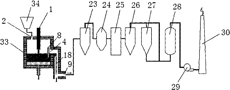
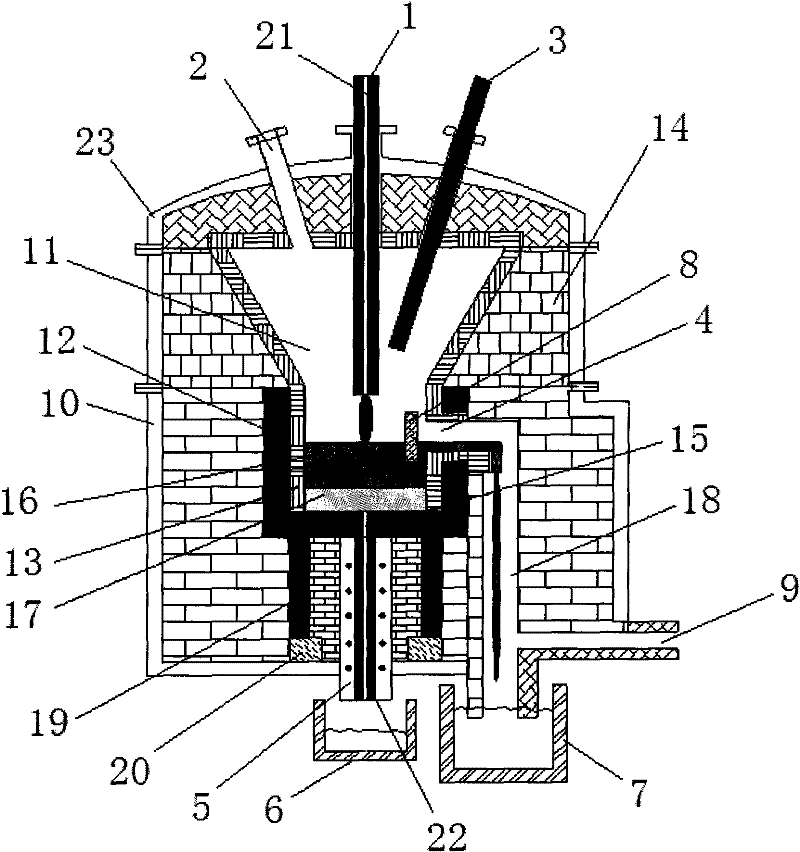
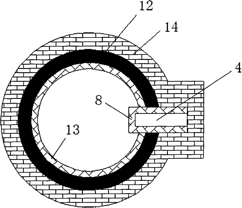
[0027] see figure 1 , 23. A device for thermal plasma treatment of solid waste includes a plasma melting pyrolysis furnace, the furnace body includes a furnace body 10 and a furnace cover 23 that are interlocked, and the middle part of the furnace body 10 is provided with a conductive crucible 12, The conductive crucible 12 is lined with a high-temperature refractory material 13 to form a furnace 11 with a cylindrical lower part and an inverted conical upper part. The furnace cover 23 is provided with a plurality of through holes extending above the furnace, two of which are Cathode 1 and anode 3 pass through the through holes respectively, and are pulled by the electrode lifting mechanism to move up and down. The lower ends of cathode and anode 1 and 3 extend into the furnace 11, and the upper ends are respectively connected to the negative pole and the arc DC power supply through cables. The center of the positive electrode and the cathode 1 has a hole 21 penetrating from t...


PUM


Abstract

The invention discloses a device and method for treating solid waste with thermal plasma, which includes a plasma melting pyrolysis furnace, a thermal plasma generating device, a working gas preparation and supply device, a feeding device, slag discharge and molten metal Emission device, exhaust gas purification treatment system and corresponding measurement and control system. The invention can completely destroy the toxic and harmful organic components in various solid wastes, prevent them from being re-synthesized, and at the same time basically convert the wastes into useful gases, stable, non-leaching toxic glassy slag and recyclable Metal components; and the amount of flue gas generated during the disposal process is very small, the purity of the usable gas is higher, the cost of tail gas purification is lower, and the tail gas can meet the emission requirements of air quality standards after purification.

Description

technical field [0001] The invention relates to the field of a device and method for treating solid waste by using arc thermal plasma high-temperature melting and pyrolysis. Background technique [0002] The amount of solid waste generated globally is increasing at an alarming rate. The solid waste generated every year is huge, of various types, complex in nature, and seriously polluted. Traditional disposal methods, such as landfill, have become more and more limited due to the limitation of landfill space. increasingly incompatible with the requirements of environmental development. As a very promising technology, solid waste incineration is more and more used in the disposal of solid waste due to its high volume reduction ratio and the ability to use the heat generated by incineration to generate electricity. However, the secondary pollution generated during the incineration process more and more people's attention. For example, a large amount of fly ash and ash will be...

Claims


Application Information

Patent Timeline
Patent Type & Authority Patents(China)
IPC IPC(8): B09B3/00
Inventor 孟月东倪国华匡靖安
Owner 安徽中科华炬环保科技有限公司
Learn More