Special optical cable for optical energy transmission

A technology of optical cable and light energy, which is applied in the direction of fiber mechanical structure, etc., can solve the problems of inability to carry out long-distance transmission, complex construction, building damage, etc., and achieve indoor lighting, heating and heating, proper material selection, and reasonable structural design Effect

Inactive Publication Date: 2010-04-21
XIAN DAISEN ELECTRONICS TECH
View PDF0 Cites 0 Cited by
  • Summary
  • Abstract
  • Description
  • Claims
  • Application Information

AI Technical Summary

Problems solved by technology

[0002] At present, the transmission of sunlight is mainly carried by light pipes or optical fibers. These two transmission tools have the following disadvantages in use: 1. The light pipe is used to transmit the light collected by the solar concentrator to the room for lighting. In some places, due to the large diameter of the pipe, the building must be opened during use, the construction is more complicated, and it will cause great damage to the building; on the other hand, the transmission distance of the light pipe is generally short, and it cannot be used for long-distance transmission. ; At the same time, because the light guide is generally made of hard materials, the bending can only be turned in a straight line, which makes large-scale application and promotion inconvenient
At present, although the application of focusing sunlight into optical cables is quite extensive, there are few studies on optical cables dedicated to optical energy transmission.

Method used


Image

  • Special optical cable for optical energy transmission
  • Special optical cable for optical energy transmission
  • Special optical cable for optical energy transmission

Examples


Embodiment Construction

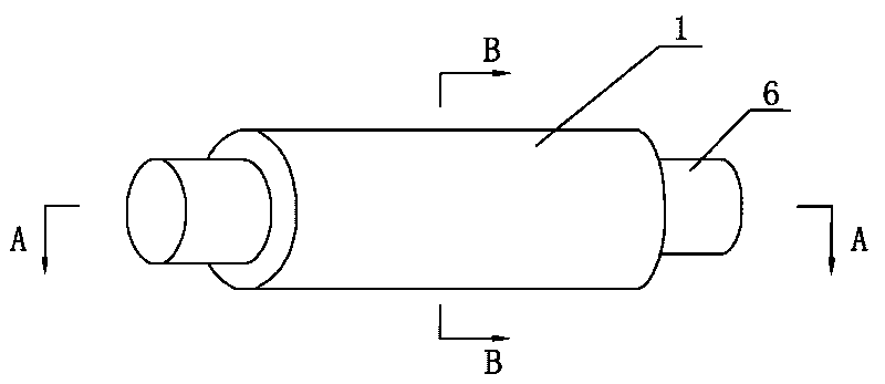
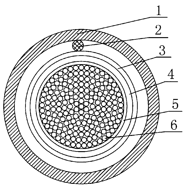
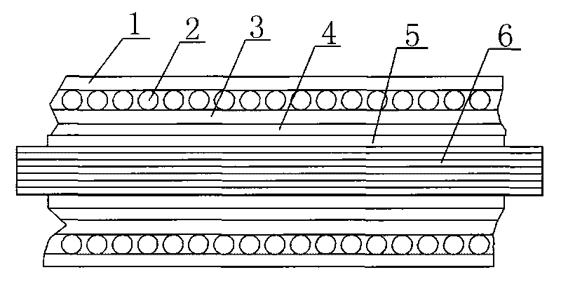
[0020] Such as figure 1 and image 3 , a special optical cable for optical energy transmission according to the present invention, comprising an optical fiber body and an optical cable PE expansion sleeve 1 arranged outside the optical fiber body, and the optical cable PE expansion sleeve 1 is sequentially provided with spring-shaped strengthening members 2 tightly wrapped with each other from the outside to the inside , water-blocking sleeve 3, heat-insulating sleeve 4 and reflective sleeve 5, and the optical cable PE expansion sleeve 1 and the spring-like reinforcement 2 are tightly wrapped. In this embodiment, the optical fiber body is composed of an optical fiber core 6 that is closely connected and covered with a transparent heat-resistant coating, wherein the transparent heat-resistant coating refers to a film coating made of PET material to protect the optical fiber core surface, and the optical fiber core 6 is made of quartz and glass. Such as figure 2 As shown, th...


PUM


Abstract

The invention discloses a special optical cable for optical energy transmission, which comprises an optical fiber body and an optical cable PE expansion sleeve arranged outside the optical fiber body. The optical cable PE expansion sleeve is provided with a spring-shaped reinforcing element, a water blocking sleeve, an insulating sleeve and a reflection sleeve which are tightly wrapped with each other in turn from the outside to the inside; and the optical cable PE expansion sleeve is tightly wrapped with the spring-shaped reinforcing element. The special optical cable for the optical energy transmission has the advantages of reasonable structural design and high transmission efficiency, and can well realize the effects of indoor illumination, warming, heating and the like.

Description

technical field [0001] The invention belongs to the technical field of optical cables, in particular to a special optical cable for optical energy transmission used for long-distance transmission of sunlight or other thermal energy light. Background technique [0002] At present, the transmission of sunlight is mainly carried by light pipes or optical fibers. These two transmission tools have the following disadvantages in use: 1. The light pipe is used to transmit the light collected by the solar concentrator to the room for lighting. In some places, due to the large diameter of the pipe, the building must be opened during use, the construction is more complicated, and it will cause great damage to the building; on the other hand, the transmission distance of the light pipe is generally short, and it cannot be used for long-distance transmission. Simultaneously, because the light guide generally adopts the processing of hard materials, the bending can only be a straight lin...

Claims


Application Information

Patent Timeline
Patent Type & Authority Applications(China)
IPC IPC(8): G02B6/44
Inventor 王学锋
Owner XIAN DAISEN ELECTRONICS TECH
Why Eureka
Try Eureka