Grid drive circuit of insulated grid device

A technology for gate drive circuits and insulated gate devices, which is applied in the directions of instruments, electrical components, and electrical variables, etc., can solve the problems of false conduction failure of insulation gate devices, inability to effectively drive high-power insulation gate devices, etc., so as to eliminate false conduction. , The effect of solving insufficient driving current and ensuring stability

Inactive Publication Date: 2011-09-14
北京航星力源科技有限公司
View PDF0 Cites 0 Cited by
  • Summary
  • Abstract
  • Description
  • Claims
  • Application Information

AI Technical Summary

Problems solved by technology

[0004] The purpose of the present invention is to provide a gate drive circuit for an insulated gate device, aiming at the problems of misconduction failure of the insulated gate device and the inability to effectively drive high-power insulated gate devices in the prior art. Synchronous drive pulse, positive and negative high current drive, simple circuit

Method used


Image

  • Grid drive circuit of insulated grid device
  • Grid drive circuit of insulated grid device
  • Grid drive circuit of insulated grid device

Examples


Embodiment Construction

[0020] The content and specific implementations of the present invention will be described in further detail below in conjunction with the drawings.

[0021] The gate drive circuit of the present invention can be used to drive any other types of devices, including but not limited to field effect transistors (FET), insulated gate bipolar transistors (IGBT) and metal oxide semiconductor (MOS) controlled thyristors (MCT) In addition, one gate drive circuit can drive one or more insulated gate devices (for example, multiple insulated gate devices operating in parallel).

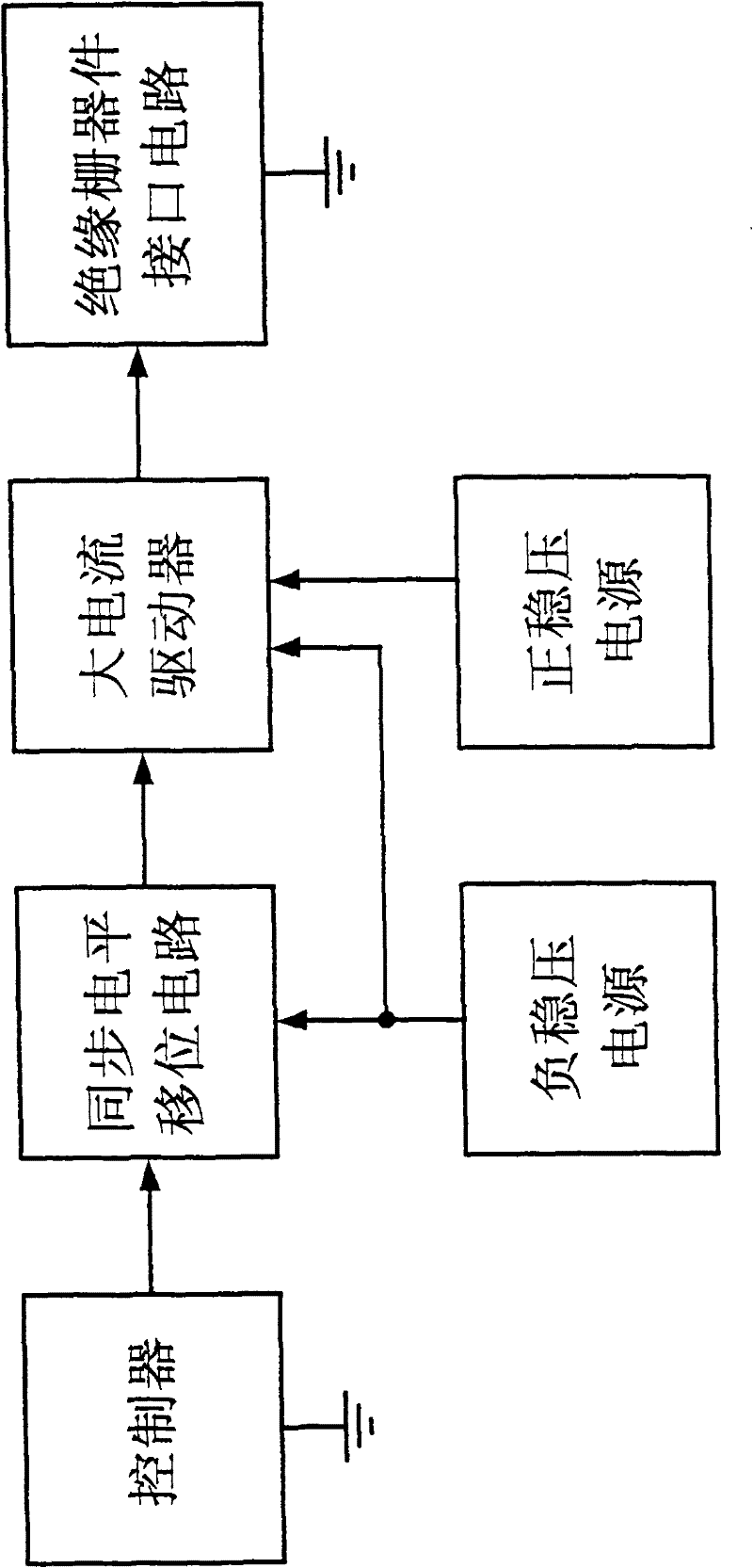
[0022] The gate drive circuit structure of an insulated gate device of the present invention is as figure 1 As shown, it includes a controller, a synchronous level shift circuit, a current driver, and an insulated gate device interface circuit connected in sequence; a positive stabilized power supply and a negative stabilized power supply connected to the current driver at the same time, the negative stabilized power s...


PUM


Abstract

The invention relates to a grid drive circuit of an insulated grid device and a working method thereof. The grid drive circuit of the insulated grid device is characterized by comprising a controller, a synchronous level shifting circuit, a current drive and an insulated grid device interface circuit which are sequentially connected, as well as a positive voltage-stabilizing power supply and a negative voltage-stabilizing power supply which are connected with the current drive; the negative voltage-stabilizing power supply is also connected with the synchronous level shifting circuit; and thecontroller and the insulated grid device interface circuit are respectively grounded. The invention has the characteristics of negative bias drive, synchronization maintenance of drive pulse, capability of positive and negative heavy current drive and concise circuit, can be widely applied in the grid drive circuit of the insulted grid device and particularly used for solving the problem of effective drive of the insulated grid device in an active power factor correction circuit.

Description

Technical field [0001] The invention belongs to the technical field of power conversion products, and particularly relates to the design of a gate drive circuit of an insulated gate device. Background technique [0002] At present, the development of power electronic technology and products is changing with each passing day, especially green energy-saving and environmentally friendly products and new energy products, such as: active power factor correction (APFC) communication power system, uninterruptible power supply (UPS) system, solar power system, wind energy Power generation systems, etc. The power conversion devices in these products generally use insulated gate devices. "Insulated gate devices" refer to a class of devices, including, but not limited to, field effect transistors (FET), metal oxide semiconductor field effect transistors (MOSFET ), insulated gate bipolar transistor (IGBT), metal oxide semiconductor (MOS) controlled thyristor (MCT), etc. The characteristics o...

Claims


Application Information

Patent Timeline
Patent Type & Authority Patents(China)
IPC IPC(8): H02M3/335H02M1/42
CPCY02B70/126Y02B70/10Y02P80/10
Inventor 谭富传姚淑珍
Owner 北京航星力源科技有限公司
Why Eureka
Try Eureka