Supercharge Your Innovation With Domain-Expert AI Agents!

Calibration device of binocular vision navigation system of lunar surface vehicle

A navigation system and binocular vision technology, applied in the direction of measuring devices, instruments, etc., can solve the problems of insufficient square grid image extraction accuracy, decreased calibration accuracy of the calibration board, and poor stability of the calibration board, so as to ensure the control grid High precision, high uniformity, adjustable brightness effect

Active Publication Date: 2010-04-28
BEIJING INST OF CONTROL ENG
View PDF0 Cites 14 Cited by
  • Summary
  • Abstract
  • Description
  • Claims
  • Application Information

AI Technical Summary

Problems solved by technology

[0003] The traditional calibration method uses a flat grid calibration board, which has the following disadvantages: the extraction accuracy of the square grid image is not enough, and the high-precision calibration of the camera cannot be completed; as the size of the calibration board becomes larger, the stability of the calibration board becomes worse , the instability of the calibration plate during the calibration process will lead to a decrease in calibration accuracy, and even cause wrong results; due to the lack of spatial information in the calibration calculation process using a two-dimensional calibration plate, it will produce mirror results for the orientation elements outside the camera, causing calculation mistake

Method used


Image

  • Calibration device of binocular vision navigation system of lunar surface vehicle
  • Calibration device of binocular vision navigation system of lunar surface vehicle
  • Calibration device of binocular vision navigation system of lunar surface vehicle

Examples


Embodiment Construction

[0019] Below in conjunction with accompanying drawing and specific embodiment the present invention is described in further detail:

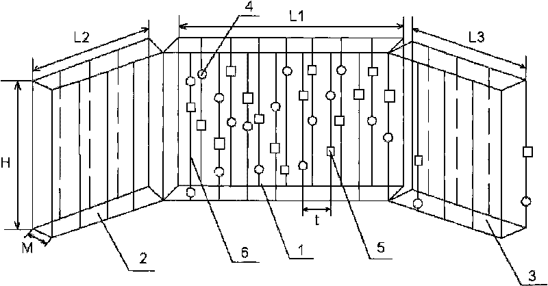
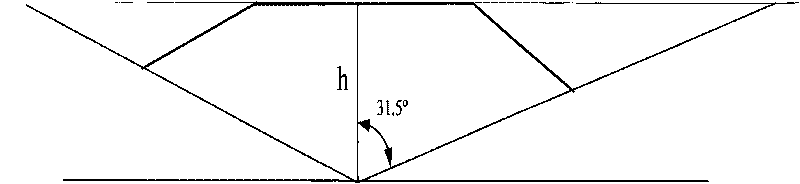
[0020] like figure 1 As shown, the calibration device mainly includes a calibration frame, a retroreflection measurement mark 4, a coding mark 5 and a ring light source. The calibration frame includes the main frame 1, the left auxiliary frame 2 and the right auxiliary frame 3 of the same size. The height H and width M of the frame 3 are the same, the angles between the left auxiliary frame 2 and the right auxiliary frame 3 and the main frame 1 are all obtuse angles, the sum of the lengths of the three frames l and the distance h between the camera and the main frame 1 The relationship between them is l=2htan(w), the length L1 and the height H of the main frame 1 are equal to the distance h between the calibration camera and the main frame 1, and multiple columns of installation bars are arranged staggeredly on the front surface and the rear su...


PUM

PropertyMeasurementUnit
Diameteraaaaaaaaaa

Abstract

The invention relates to a calibration device of a binocular vision navigation system of a lunar surface vehicle, which comprises a calibration frame, return light reflection and measurement signs, coding signs and an annular light source, wherein the calibration frame comprises a main frame, a left auxiliary frame and a right auxiliary frame, the left auxiliary frame and the right auxiliary frame have the same size, a plurality of columns of installation strip frames are arranged on the front surface and the back surface of the calibration frame in a staggered way, a plurality of return light reflection and measurement signs are arranged on each column of installation strip frames, at least one punctiform coding sign is arranged in each column of return light reflection and measurement signs, and the annular light source comprises two groups of LED light sources and is arranged at the position of the front of the calibration frame. The invention adopts the design of a three-dimensional stereo frame structure, solves the defect existing in a two-dimensional calibration plate, solves the problem of low extraction accuracy of the digital images of lattice calibration signs by installing a plurality of columns of return light reflection and measurement signs in a three-dimensional stereo frame, realizes the automatic identification of a calibration field by arranging at least one punctiform coding sign in each column of return light reflection and measurement signs and can enhance the calibration accuracy by the annular LED light source.

Description

technical field [0001] The invention relates to a navigation system calibration device, in particular to a lunar rover binocular vision navigation system calibration device. Background technique [0002] The binocular visual navigation of the lunar rover is one of the navigation technologies used in my country's lunar exploration program. The binocular visual navigation system of the lunar rover is mainly composed of two digital cameras, a cube mirror and a system bracket. The cameras are fixed at both ends of the bracket, and the cube mirror is fixed in the middle of the two cameras. Because the binocular vision navigation of the lunar rover mainly relies on two cameras to obtain external information at the same time, and then determine its own navigation method, mainly including visual measurement, terrain matching, path planning and other technologies. In the binocular vision navigation system, the comprehensive calibration of the system is the key technology to realize ...

Claims


Application Information

Patent Timeline
IPC IPC(8): G01C25/00
Inventor 李春艳王立卢欣史广清范生宏石霄亮
Owner BEIJING INST OF CONTROL ENG
Features
  • R&D
  • Intellectual Property
  • Life Sciences
  • Materials
  • Tech Scout
  • Unparalleled Data Quality
  • Higher Quality Content
  • 60% Fewer Hallucinations
Learn More