Automatic positioning and cutting system for photographic identification

A cutting system and automatic positioning technology, applied in the direction of instruments, electrical digital data processing, digital control, etc., can solve the problems of not being able to automatically adjust and adapt

Active Publication Date: 2010-04-28
BEIJING KAITIAN TECH
View PDF1 Cites 1 Cited by
  • Summary
  • Abstract
  • Description
  • Claims
  • Application Information

AI Technical Summary

Problems solved by technology

[0003] The purpose of the present invention is to provide an automatic positioning and cutting system for camera recognition, which overcomes the deficiency that the above-mentioned products cannot be automatically adjusted and adapted when in use.

Method used


Image

  • Automatic positioning and cutting system for photographic identification
  • Automatic positioning and cutting system for photographic identification
  • Automatic positioning and cutting system for photographic identification

Examples


Embodiment Construction

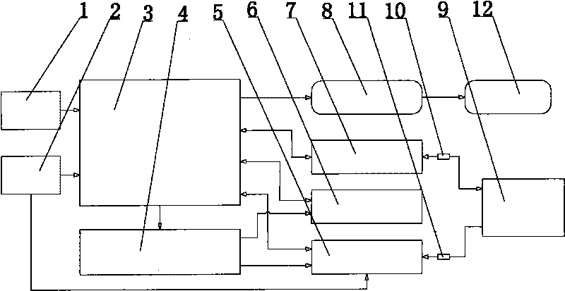
[0048] like figure 1 As shown, the camera recognition automatic positioning and cutting system described in the embodiment of the present invention mainly includes a main control MCU module 3 and a chip selection and logic module 4, and the main control MCU module 3 is input and connected to the crystal oscillator module 1 and the reset module 2. The output of the main control MCU module 3 is connected to the To / From drive module 8, and the output of the To / From drive module 8 is connected to the motor 12. The main control MCU module 3 can send the control signal of the motor 12 through the To / From drive module 8 to obtain the drive signal of the motor 12. , so as to control the motor 12; the input / output of the main control MCU module 3 is connected to the IO expansion module 5, the external SRAM module 6 and the serial port level conversion module 7, and the external SRAM module 6 can provide the required chips for the main control MCU module 3 External SRAM support; IO expa...


PUM


Abstract

The invention relates to an automatic positioning and cutting system for photographic identification, which comprises a main control MCU module and a chip selection logic module, wherein the main control MCU module is connected with a To / From driving module, and the To / From driving module is connected with a motor; the main control MCU module is connected with an IO extension module, an external SRAM module and a serial port level conversion module, the IO extension module is in input connection with a reset module, and the IO extension module is connected with a PC module; the serial port level conversion module is connected with the PC module; the main control MCU module is in output connection with the chip selection logic module, and the chip selection logic module is connected with the IO extension module and the external SRAM module respectively; and an automatic re-positioning module and a matching module are arranged in the PC module. The automatic positioning and cutting system has the beneficial effects that the automatic positioning and cutting system has the automatic adjustment function and can correct the position deviation, the angle deviation and the like, automatically generate a path and identify the deformation, the position derivation and the rotation of a work piece in a real time manner.

Description

technical field [0001] The invention relates to a laser cutting system, in particular to a camera recognition automatic positioning and cutting system for positioning and cutting trademarks, signs and other work that can be recognized by cameras. Background technique [0002] Existing laser cutting systems can only process workpieces according to the designed cutting path. When the workpiece itself is deformed, shifted or rotated, the system cannot automatically adapt, so it cannot process such workpieces. This affects the use of the product to a large extent and cannot meet market demand. Contents of the invention [0003] The object of the present invention is to provide an automatic positioning and cutting system for camera recognition, which overcomes the deficiency that the above-mentioned products cannot be automatically adjusted and adapted when in use. [0004] The purpose of the present invention is to realize through the following technical solutions: [0005] ...

Claims


Application Information

Patent Timeline
Patent Type & Authority Applications(China)
IPC IPC(8): G05B19/33G06F13/40G05B19/37
Inventor 黄新营
Owner BEIJING KAITIAN TECH
Why Eureka
Try Eureka