Rotary inertia identification method for permanent magnet synchronous motor AC servo system

A technology of permanent magnet synchronous motor and moment of inertia, which is applied in the field of moment of inertia identification, can solve the problems that the identification result deviates from the real result, errors, and cannot identify the change of moment of inertia, etc., and achieves the effect of high identification accuracy

Active Publication Date: 2010-04-28
SHANGHAI STEP ELECTRIC +1
View PDF1 Cites 32 Cited by
  • Summary
  • Abstract
  • Description
  • Claims
  • Application Information

AI Technical Summary

Problems solved by technology

[0005] A. When the AC servo system is accelerating and decelerating during the identification process, if its load torque changes irregularly and in real time, that is to say, when the load torque during the acceleration process is asymmetrical to the load torque during the deceleration process, or When the difference is very large, it will lead to the phenomenon that the identification result is far from the real result;
[0006] B. If the moment of inertia of the system changes during acceleration and deceleration, the above-mentioned moment of inertia identifier cannot identify the change of moment of inertia, and may even identify a wrong result

Method used


Image

  • Rotary inertia identification method for permanent magnet synchronous motor AC servo system
  • Rotary inertia identification method for permanent magnet synchronous motor AC servo system
  • Rotary inertia identification method for permanent magnet synchronous motor AC servo system

Examples


Embodiment Construction

[0030] A preferred embodiment will be given below, and the present invention will be described more clearly and completely in conjunction with the accompanying drawings.

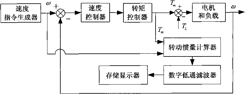
[0031] Such as figure 1 As shown, the moment of inertia identifier of the AC permanent magnet synchronous motor servo system adopted by the inventive method comprises the following seven parts: speed command generator, speed controller, torque controller, moment of inertia calculator, digital low-pass filter , storage display, motor and load. The torque loop is the inner loop of the speed loop. One output of the speed command generator is used as the input of the speed controller, and the other output is used as the input of the moment of inertia calculator. The output of the speed controller is used as the input of the torque controller. The output of the controller is used as the input of the motor and the load. The electromagnetic torque overcomes the load torque to make the motor drive the load to rotat...


PUM


Abstract

The invention discloses a rotary inertia identification method for a permanent magnet synchronous motor AC servo system, which adopts a speed command generator, a motor and a load, and comprises the following steps that: the permanent magnet synchronous motor AC servo system generates enable which has the rotary inertia identification function, and a user sets the rotary inertia identification duration; the speed command generator generates a uniform acceleration command of a first acceleration in the forward direction to make the motor accelerated to a first rotating speed; the speed command generator generates a uniform acceleration command of a second acceleration in the forward direction to make the motor accelerated to a second rotating speed; the speed command generator generates a uniform acceleration command of a third acceleration in the forward direction to make the motor reduced to the first rotating speed; and the speed command generator generates a uniform acceleration command of a fourth acceleration in the forward direction to make the motor reduced to a zero rotating speed, and a forward-direction rotary inertia identification cycle is completed. The method ensures high identification precision in the rotary inertia identification process.

Description

technical field [0001] The invention relates to an AC permanent magnet synchronous motor servo system, in particular to a rotational inertia identification method of the AC permanent magnet synchronous motor servo system. Background technique [0002] In the actual production site, the AC permanent magnet synchronous motor servo system has the problem of mechanical and electrical cooperation. When the moment of inertia of the load carried by the motor changes, it will have a significant impact on the servo characteristics of the system. An increase in the moment of inertia will slow down the response of the system, which will easily cause system instability and cause climbing phenomena; although a decrease in the moment of inertia will speed up the dynamic response speed of the system, it will cause the speed to overshoot or even oscillate. In order to achieve good dynamic and static characteristics of high-precision control of the servo system, it is necessary to identify ...

Claims


Application Information

Patent Timeline
Patent Type & Authority Applications(China)
IPC IPC(8): H02P23/14
Inventor 张扬杨明李悦韡刘伟东
Owner SHANGHAI STEP ELECTRIC
Why Eureka
Try Eureka