Supercharge Your Innovation With Domain-Expert AI Agents!

Spherical surface defect detection method based on machine vision

A defect detection and sphere technology, used in instruments, measuring devices, scientific instruments, etc., can solve the problems of increasing maintenance costs and complex structure of the detection system, and achieve the effect of low maintenance costs, simple structure of detection equipment, and improved inspection efficiency.

Inactive Publication Date: 2010-05-05
HENAN UNIV OF SCI & TECH
View PDF0 Cites 12 Cited by
  • Summary
  • Abstract
  • Description
  • Claims
  • Application Information

AI Technical Summary

Problems solved by technology

The steel ball detection of this system is a non-contact detection in a detection tank equipped with a service liquid. The service liquid is required to be transparent and replaced regularly, which increases the maintenance cost, and the structure of the detection system is also relatively complicated.

Method used


Image

  • Spherical surface defect detection method based on machine vision
  • Spherical surface defect detection method based on machine vision
  • Spherical surface defect detection method based on machine vision

Examples


Embodiment Construction

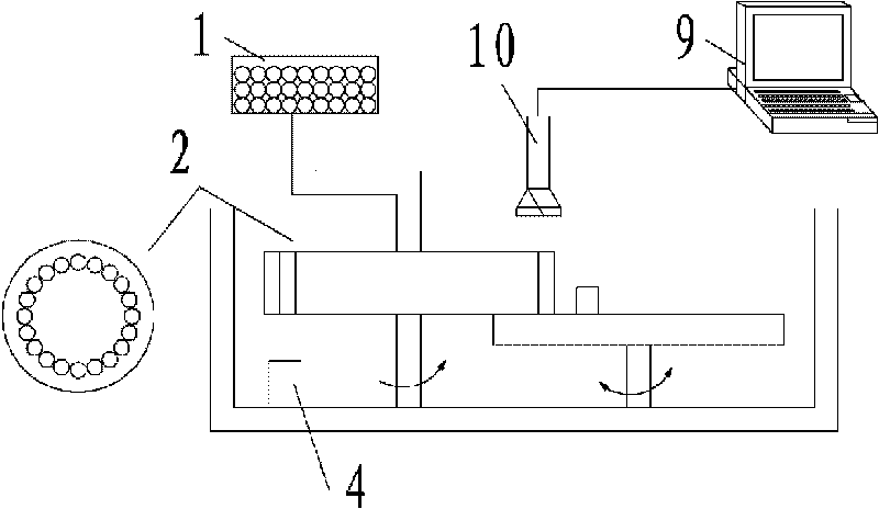
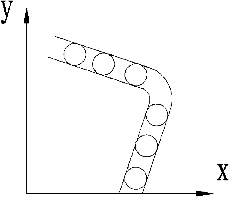
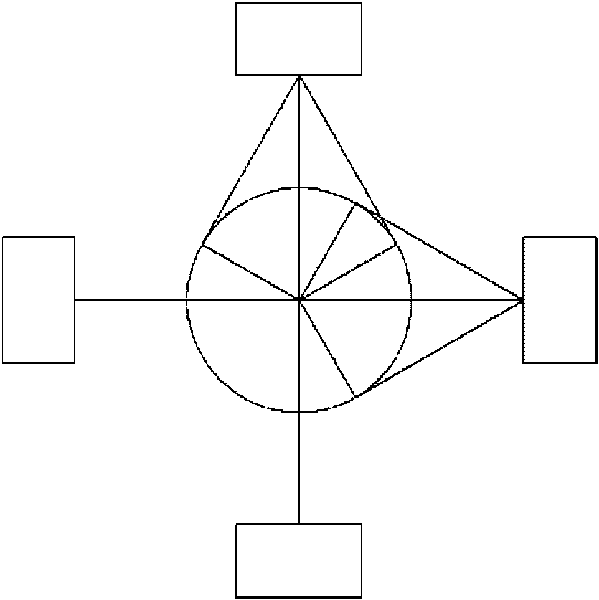
[0022] The present invention is based on the machine vision-based sphere surface defect detection method, which adopts the method of moving the sphere to be tested along the figure 2 The pure rolling is performed on the two mutually perpendicular and interconnected tracks, and a pit is set at the junction of the two tracks. When the ball moves to the junction of the two tracks, it stops rolling under the action of the pit, and then the trigger Push the ball to make it roll to another track that is perpendicular to each other. The two tracks are set vertically and the pits are set at the junction to ensure that the ball is doing pure rolling on the track. In this way, the camera set above the track collects Only the image information of the sphere can cover the entire position of the sphere, and there will be no missed acquisition areas. image 3 As shown, there are four cameras distributed on the equatorial plane of the sphere, and two branches are located on the plane perpen...


PUM


Abstract

The invention relates to spherical surface defect detection method based on machine vision. The method comprises: leading spheres to be detected to make pure rolling along straight tracks which are communicated with each other and vertically arranged at the two end parts; arranging a camera at the position just facing the tracks to acquire the image information of unfolded surfaces of the spheres; transmitting the acquired image information into an image processing system to be processed; and figuring out the position and the area of the defect. The detection method has high accuracy, and avoids undetected error caused by artificial detection and the detection difference caused by the self subjective factor of the detector. Meanwhile, a detection device adopting the detection method is simpler in structure and low in use and maintenance costs.

Description

technical field [0001] The invention relates to a method for detecting object surface defects based on machine vision, in particular to a method for detecting surface defects of a sphere based on machine vision. Background technique [0002] Bearing is a very important part in machinery industry. Its precision, motion performance and service life largely depend on the quality of the steel balls in it. The traditional surface quality inspection of bearing steel balls mainly adopts the method of manual visual inspection. This inspection method not only has a large workload, but also is easily affected by the subjective factors of the inspectors. It is easy to cause missed inspections and false inspections of bearing steel ball surface defects, and cannot Detection efficiency and accuracy. In recent years, with the development of machine vision recognition technology, many scientific research institutions have started the application research of surface defect detection based ...

Claims


Application Information

Patent Timeline
IPC IPC(8): G01N21/892
Inventor 杨建玺宋晓霞康春花
Owner HENAN UNIV OF SCI & TECH
Features
  • R&D
  • Intellectual Property
  • Life Sciences
  • Materials
  • Tech Scout
  • Unparalleled Data Quality
  • Higher Quality Content
  • 60% Fewer Hallucinations
Learn More