
Optical fiber image inverter rotary torsion processing technology

A processing technology and image inverter technology, which is applied in the field of optical fiber image inverter rotation and torsion processing, can solve problems such as poor quality of optical fiber image inverters, improve the pass rate and quality rate, solve distortion, and reduce uniformity requirements Effect

Inactive Publication Date: 2010-05-05
山西长城微光器材股份有限公司
View PDF0 Cites 7 Cited by
  • Summary
  • Abstract
  • Description
  • Claims
  • Application Information

AI Technical Summary

Problems solved by technology

[0004] In order to solve the problem of poor quality of the fiber optic inverter caused by the simple twisting method of the fiber optic inverter existing in the prior art, the present invention provides a rotating and twisting processing technology of the fiber optic inverter

Method used


Image

  • Optical fiber image inverter rotary torsion processing technology
  • Optical fiber image inverter rotary torsion processing technology

Examples


Embodiment Construction

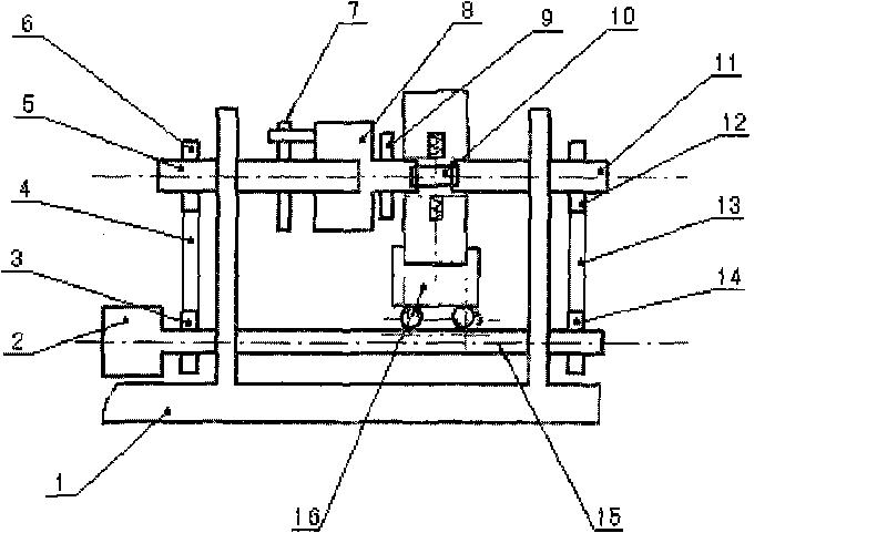
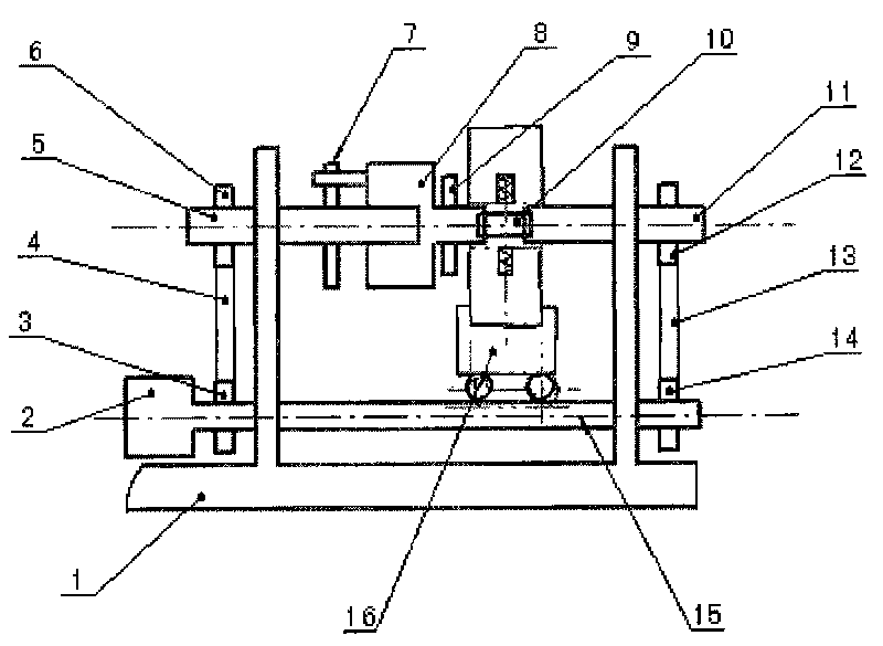
[0014] Such as figure 1 As shown, the structure of the torsion machine includes a base and a support 1. The base is provided with a motor 2 and a synchronous shaft 15 that is activated by the motor. The synchronous shaft 15 is meshed with synchronous transmission teeth 3, 4, 6; synchronous transmission teeth 14, 13 , 12, left shaft 5 and right shaft 11 are respectively pierced on the bracket, synchronous transmission teeth 3, 4, 6 drive left shaft 5, synchronous transmission teeth 14, 13, 12 drive right shaft 11, and left shaft 5 is provided with synchronization The mechanism 7, the torsion structure 8 and the resistance mechanism 9, the torsion mechanism 8 and the right shaft 11 are opposed to each other (the workpiece is connected between them). A heating furnace 16 is also provided between the left shaft 5 and the right shaft 11.

[0015] The left shaft 5 and the right shaft 11 can rotate synchronously under the driving of the synchronization shaft 15, and the left shaft 5 ca...


PUM


Abstract

The invention belongs to the technical field of manufacture of optical fiber image transmission devices, in particular to an optical fiber image inverter rotary torsion processing technology. The invention solves the problem of poor optical fiber image inverter quality brought by a simple torsion method of the optical fiber image inverter in the prior art. The technology comprises the following steps of: driving both ends of an optical fiber composite rod blank in a horizontal state to generate synchronous rotation; meanwhile, heating a optical fiber composite rod to a certain temperature and then starting to apply resistance on a driven shaft to enable the driven shaft to gradually form a certain angle difference with a driving shaft; when the difference reaches 180 DEG C, controlling the rotation speed of the driven shaft to be consistent to the rotating speed of the driving shaft so that the two shafts realize the synchronous rotation; when cooling the optical fiber composite rod blank to plate taking temperature during torsion, shutting down and taking a plate to obtain an image transmission device of which both end surfaces are differed by 180 DEG C. Compared with the prior art, by using the technical scheme, the quality and the torsion qualification rate of the optical fiber image inverter can be improved.

Description

Technical field [0001] The invention belongs to the technical field of optical fiber image transmission device manufacturing, in particular to a rotating and twisting processing technology of an optical fiber image invertor. technical background [0002] The fiber-optic imager is a kind of fiber-optic filaments arranged in a certain rule and heated and extruded. The output end face is rotated 180° around the central axis relative to the input end face, so that the image on the output end face and the image on the input end face are mutually exclusive The inverted fiber optic image transmission device is one of the core components for manufacturing low-light night vision devices. [0003] The existing general production method of optical fiber inverted device is: use static heating, static torsion, that is, the twisted fiber composite rod blank is static relative to the heating furnace when it is heated and twisted, so that the temperature unevenness around the heating furnace and ...

Claims


Application Information

Patent Timeline
Patent Type & Authority Applications(China)
IPC IPC(8): G02B6/04
Inventor 刘贞文杨红兵田群戌李勇
Owner 山西长城微光器材股份有限公司
Learn More