Camshaft flame quenching automatic heat treatment machine tool and technology

A flame quenching and camshaft technology, applied in the field of heat treatment, to achieve the effects of automatic and precise operation, strong applicability, quality assurance and stability

Active Publication Date: 2017-03-15
HEBEI UNIV OF ENG
View PDF6 Cites 0 Cited by
  • Summary
  • Abstract
  • Description
  • Claims
  • Application Information

AI Technical Summary

Problems solved by technology

[0006] The technical problem to be solved in the present invention is to provide a camshaft flame quenching automatic heat treatment machine tool and process to solve the technical problems existing in the application of the flame quenching heat treatment process to the camshaft quenching process, so as to realize the automatic and accurate operation of the camshaft flame quenching process , to ensure the quality and stability of quenching

Method used


Image

  • Camshaft flame quenching automatic heat treatment machine tool and technology
  • Camshaft flame quenching automatic heat treatment machine tool and technology
  • Camshaft flame quenching automatic heat treatment machine tool and technology

Examples


Embodiment Construction

[0032] Below in conjunction with accompanying drawing, the present invention will be described in further detail:

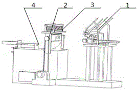
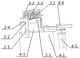
[0033] The camshaft flame quenching automatic heat treatment machine tool of the present invention includes a feeding mechanism 1, a rotating mechanism 2, a heating mechanism 3, a cooling mechanism 4 and a control mechanism arranged on the machine tool in sequence, and the control mechanism controls the coordinated operation of the various mechanisms of the machine tool. The specific structure is as figure 1 , figure 2 , image 3 , Figure 4 shown.

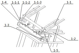
[0034]The feeding mechanism 1 of the present invention includes a sliding chute 1-1 and a feeding receiver 1-4. The function of the feeding mechanism 1 is to make the camshaft enter the rotating mechanism 2 according to the required time and order. The sliding material trough 1-1 is arranged on the machine frame body, the sliding material chute 1-1 is an upper arc structure or a straight structure, and the slid...


PUM

PropertyMeasurementUnit
depthaaaaaaaaaa
depthaaaaaaaaaa

Abstract

The invention relates to a cam shaft flame hardening automatic heat treatment machine tool. The machine tool comprises a feeding mechanism, a rotating mechanism, a heating mechanism, a cooling mechanism and a control mechanism controlling all the mechanisms of the machine tool to run cooperatively, wherein the feeding mechanism, the rotating mechanism, the heating mechanism, the cooling mechanism and the control mechanism are arranged on the machine tool in sequence. The invention further discloses a cam shaft flame hardening automatic heat treatment technology. The technology specially comprises the steps of automatic feeding, flame heating and cooling. By the adoption of the cam shaft flame hardening automatic heat treatment machine tool and technology, the technical problem of conducting automatic heat treatment on a cam shaft with the flame hardening heat treatment technology is solved, automatic precise operation is achieved during cam shaft flame hardening, hardening quality and stability are guaranteed, a feeding system and a discharging system of the cam shaft flame hardening automatic machine tool are high in automation degree, and production efficiency and economic effectiveness are further improved.

Description

technical field [0001] The invention relates to the technical field of heat treatment, in particular to a machine tool and process for flame quenching automatic heat treatment of shaft parts. Background technique [0002] The camshaft is a key component in the piston engine. The main body is a cylindrical rod with approximately the same length as the cylinder group. There are several cams on it, which are used to drive the valve and control the opening and closing of the valve. The camshaft rotates at a high speed in the engine and needs to bear a large torque, and also needs to bear periodic shock loads. The contact stress between the cam and the tappet is very large, and the relative sliding speed is also high, so the wear of the cam working surface is serious. In view of this situation, in addition to the high dimensional accuracy, small surface roughness and sufficient rigidity that the camshaft journal and the cam working surface should have, they should also have high...

Claims


Application Information

Patent Timeline
Patent Type & Authority Patents(China)
IPC IPC(8): C21D9/30C21D1/63
Inventor 朱桂英叶有才叶腾
Owner HEBEI UNIV OF ENG
Why Eureka
Try Eureka