Powder gun with continuously adjustable power outlet angle

A powder spray gun and angle technology, which is applied to spray devices, spray devices, spray discharge devices, etc., can solve the problems of low efficiency, high cost, and labor.

Inactive Publication Date: 2010-05-12
李志军
View PDF0 Cites 1 Cited by
  • Summary
  • Abstract
  • Description
  • Claims
  • Application Information

AI Technical Summary

Problems solved by technology

In practical application, for different spraying requirements, it is necessary to adjust the powder outlet angle of the powder spray gun. The deflector or several gun shafts are costly, and the operation is very troublesome and laborious, and the efficiency is low

Method used


Image

  • Powder gun with continuously adjustable power outlet angle
  • Powder gun with continuously adjustable power outlet angle
  • Powder gun with continuously adjustable power outlet angle

Examples


Embodiment Construction

[0015] The present invention will be described in detail below in conjunction with the accompanying drawings and specific embodiments.

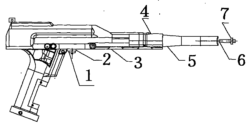
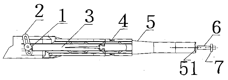
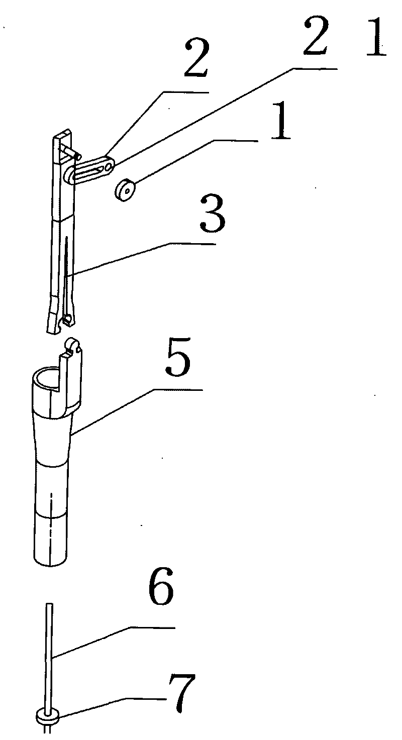
[0016] The invention provides a powder spraying gun with continuously adjustable powder outlet angle, such as figure 1 , figure 2 and image 3 As shown, it includes: a gun body, an adjusting piece 2, an adjusting piece lock nut 1, a connecting rod 3, a gun head seat 4, and a gun shaft 5; one end of the adjusting piece 2 is provided with a fixing hole 21, through which the fixing hole 21 is connected with the Said gun body rotates and cooperates, and a circular shaft is arranged above said gun body, and fixing hole 21 is connected with said circular shaft, and adjusting sheet 2 can rotate around this rotating shaft like this, and said adjusting sheet is also provided with a sliding track, as figure 2 The hollow formed horizontally in the middle of the adjusting piece is the sliding track, and one end of the connecting rod 3 is slidably mat...


PUM


Abstract

The invention discloses a powder gun with a continuously adjustable power outlet angle, which is characterized by comprising a gun body, an adjustment sheet, an adjustment sheet lock nut, a connecting bar, a gun head seat and a gun bar. The connecting bar and the gun bar are pushed by touching the adjustment sheet so as to adjust the relative distance between the gun bar and a flow deflector, so that the purpose of adjusting the powder outlet angle is achieved; and the powder gun has convenient operation and low cost.

Description

technical field [0001] The invention relates to the field of electrostatic spraying, in particular to a powder spraying gun with continuously adjustable powder output angle. Background technique [0002] In the prior art, the electrostatic powder spraying gun is to apply high-voltage electricity to the nozzle of the spray gun. When the powder mixed with the high-pressure airflow passes through the nozzle of the spray gun, it will be charged with a negative charge and fly to the workpiece, and the workpiece is grounded as the positive pole. Under the action of positive and negative electrostatic attraction, it is evenly adsorbed on the surface of the workpiece, and it is melted and solidified (or plasticized) into a coating after being heated in an oven at a certain temperature. The current powder spray gun mainly includes a gun shaft, a mixed powder air pipe arranged in the inner cavity of the gun shaft, a discharge needle sleeve arranged in front of the gun shaft, and a dis...

Claims


Application Information

Patent Timeline
Patent Type & Authority Applications(China)
IPC IPC(8): B05B5/03B05B12/00B05B15/00
CPCB05B5/0533B05B1/3073
Inventor 李志军
Owner 李志军
Why Eureka
Try Eureka