Solid solution treatment device for U-shaped heat exchange tubes

A technology of solid solution treatment and heat exchange tubes, applied in heat treatment furnaces, heat treatment equipment, quenching devices, etc., can solve problems such as potential safety hazards of conductors, safety accidents, inconsistent distance between positioning points, etc., and achieve the effect of avoiding shaking

Pending Publication Date: 2020-07-03
山东齐鲁石化机械制造有限公司
View PDF0 Cites 0 Cited by
  • Summary
  • Abstract
  • Description
  • Claims
  • Application Information

AI Technical Summary

Problems solved by technology

[0004] First of all, when the traditional U-shaped heat exchange tube is performing solution treatment, because the shape and specification of the clamping block are fixed, it can only effectively clamp and limit the U-shaped heat exchange tube of the same type and specification, and Since the distance between the two ends of the U-shaped tube is different due to the different models and specifications, the distance between the positioning points to be clamped between the two is also inconsistent, which further limits the scope of use of the traditional U-shaped heat exchange tube clamping mechanism. Use has brought great inconvenience;
[0005] Secondly, the opening and closing of the two clamping seats of the traditional U-shaped heat exchange tube clamping mechanism is completely through manual operation. Although an insulating sleeve is provided on the handle, the operation is still cumbersome and the operator is easy to touch. The risk of conductors posing a safety hazard;
[0006] Finally, the traditional U-shaped heat exchange tube clamping mechanism lacks a related locking mechanism, and the installation of the U-shaped tube is not firm, which is likely to cause safety accidents;

Method used


Image

  • Solid solution treatment device for U-shaped heat exchange tubes
  • Solid solution treatment device for U-shaped heat exchange tubes
  • Solid solution treatment device for U-shaped heat exchange tubes

Examples


Embodiment

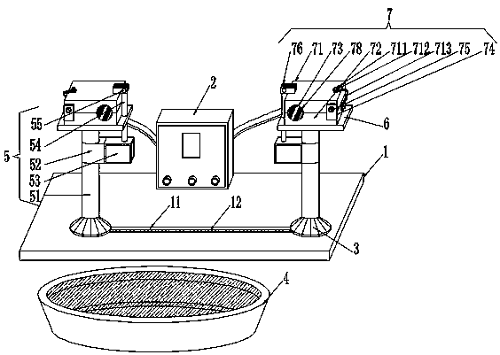
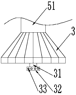
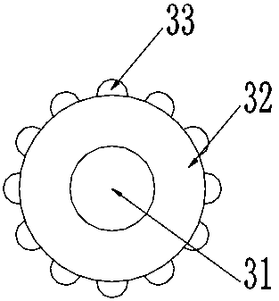
[0031] A U-shaped heat exchange tube solid solution treatment device, comprising a base 1, a power supply box 2, a sliding seat 3, a cooling pool 4, a pneumatic opening and closing mechanism 5, a carrier plate 6 and a clamping heating mechanism 7, and the upper end surface of the base 1. A power supply box 2 is fixedly installed near the center of one side, and two sliding seats 3 are slidably installed on the base 1. The specifications of the two sliding seats 3 are the same and the connecting line between each other is parallel to the power box 2, and the base 1 One side is provided with a cooling pool 4, the tops of the two sliding seats 3 are fixedly installed with a pneumatic opening and closing mechanism 5, the tops of the two pneumatic opening and closing mechanisms 5 are fixedly installed with a carrier plate 6, and the upper ends of the two carrier plates 6 are fixed A clamping heating mechanism 7 is installed. The two clamping heating mechanisms 7 have the same specifi...


PUM


Abstract

The invention discloses a solid solution treatment device for U-shaped heat exchange tubes. The device comprises a base, a power box, two sliding seats, a cooling pool, pneumatic opening and closing mechanisms, carrier plates and clamping and heating mechanisms, wherein the power box is fixedly installed at a position, close to one side, of the center of the upper end face of the base; the two sliding seats are slidably installed on the base, and are identical in specification, and a connecting wire between the two sliding seats is parallel with the power box; the cooling pool is arranged on one side of the base; the carrier plates are fixedly installed on tops of the two pneumatic opening and closing mechanisms, the sliding seats supporting the two clamping seats can slide freely on the base through balls, the U-shaped heat exchange tubes of different specifications can be conveniently placed in clamping grooves by adjusting the relative distance between two installation points, so that manual operation is avoided, operation steps are reduced, operation safety is increased, and the problem that safety accidents are easily caused because lack of relevant locking mechanisms betweenthe traditional U-shaped heat exchange tube clamping mechanisms and loose installation of the U-shaped tubes is solved.

Description

Technical field [0001] The invention belongs to the technical field of U-shaped heat exchange tube solid solution treatment, and is specifically a U-shaped heat exchange tube solid solution treatment device. Background technique [0002] In the production of heat exchangers, the manufacture of stainless steel U-shaped heat exchange tube bundles occupies a considerable proportion. When the use environment has high requirements for the corrosion resistance of the heat exchange tubes, the U-shaped heat exchange is generally used in the production process. The bending part of the tube takes special processing measures to restore the material structure and performance of the bend of the heat exchange tube to (or close to) the original delivery state as much as possible (because the cold deformation during the bending process of the U-shaped tube will cause the material Deterioration of organization and performance). [0003] The traditional U-shaped heat exchange tube solid solution tr...

Claims


Application Information

Patent Timeline
Patent Type & Authority Applications(China)
IPC IPC(8): C21D9/08C21D1/63
CPCC21D1/63C21D9/0018C21D9/0025C21D9/0062C21D9/08C21D9/085
Inventor 汪沛李飞李宇龙韩波高峰喜
Owner 山东齐鲁石化机械制造有限公司
Why Eureka
Try Eureka