Supercharge Your Innovation With Domain-Expert AI Agents!

Sprue cup for smelting alloy

A pouring cup and alloy technology, which is applied to metal processing equipment, casting melt containers, casting equipment, etc., can solve the problems of limited filtering effect of the filter screen, affecting the quality of alloys, removal, etc., to achieve good application prospects, improve quality, The effect of reducing the impurity content

Inactive Publication Date: 2011-04-06
SHENYANG LIMING AERO-ENGINE GROUP CORPORATION
View PDF0 Cites 0 Cited by
  • Summary
  • Abstract
  • Description
  • Claims
  • Application Information

AI Technical Summary

Problems solved by technology

When the existing sprue cup is in use, when the melt enters the filter port, the filter can only be used to filter the impurities. When there are many fine impurities, the filtering effect of the filter is limited, especially when the returned material is used to smelt the alloy. Fine oxide particles will flow into the alloy with the alloy liquid, thereby affecting the quality of the alloy, reducing the pass rate of alloy castings and increasing production costs
How to remove most of the impurities in the alloy melt before the impurities enter the filter screen, there is currently no simple and effective method for industrial production

Method used


Image

  • Sprue cup for smelting alloy
  • Sprue cup for smelting alloy
  • Sprue cup for smelting alloy

Examples


Embodiment 1

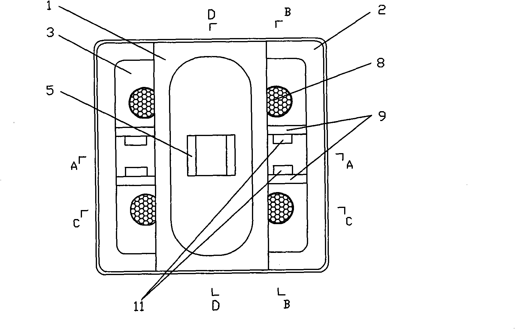
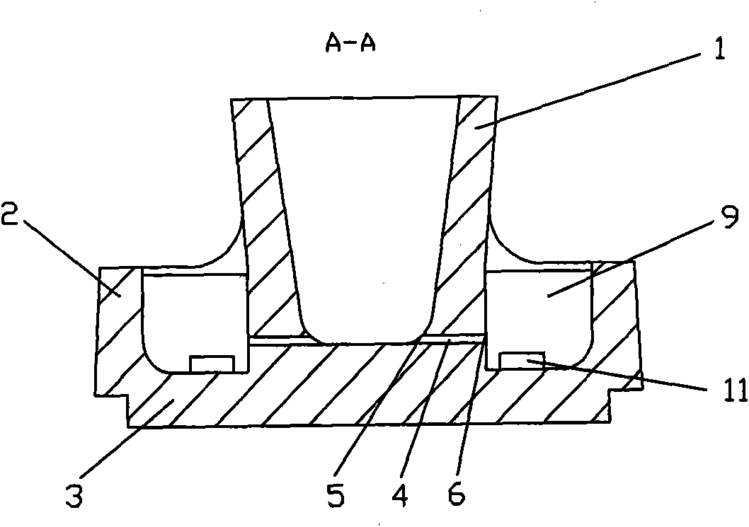
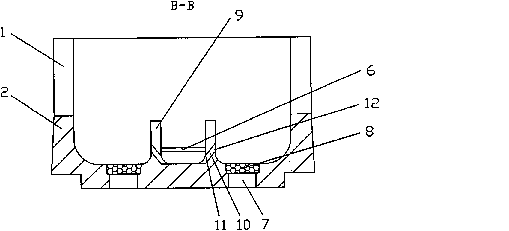
[0021] The structure of sprue cup for alloy melting is as follows: figure 1 , figure 2 , image 3 , Figure 4 , Figure 5 As shown, the sprue cup is mainly composed of an inner cup wall 1, an outer cup wall 2 and a bottom plate 3 shared by both. The bottom plate 3 is provided with a filter port 7, and a filter screen 8 is provided on the filter port 7. The inner cup The bottom of the wall 1 is provided with two melt channels 4, the opening of the melt channel 4 on the inner side of the inner cup wall 1 is the melt channel inlet 5, and the opening of the melt channel 4 on the outer side of the inner cup wall is the melt Passage exit 6.

[0022] Four dams 9 are arranged between the inner cup wall 1 and the outer cup wall 2, and the dams 9 are located between the melt channel outlet 6 and the filter port 7; the level height of the dams 9 is smaller than that of the outer cup wall 2, The height difference is 2mm. The side of the dam 9 opposite to the outlet 6 of the melt ch...

Embodiment 2

[0026] The structure of the sprue cup for alloy smelting is the same as in Example 1, except that the horizontal height of the dam is equal to the horizontal height of the outer cup wall; the height difference between the highest point of the entrance of the slag channel and the lowest point of the outlet of the slag channel is 5mm.

Embodiment 3

[0028] The structure of the sprue cup for alloy smelting is the same as that in Embodiment 1, except that the height difference between the highest point of the entrance of the slag holding channel and the lowest point of the exit of the slag holding channel is 10mm.

[0029] The above-mentioned sprue cup is used for pouring, and the alloy melt is poured into the inner cup wall, and the floating impurities are in the dam and do not enter the filter port. If the molten steel is very dirty and contains large pieces of slag inclusions to block the slag holding port, the alloy liquid will flow into the filter port through the top of the dam, reducing the problem of fire escape. Compared with the original sprue cup without a dam, the impurities in the alloy ingot are significantly reduced, and the reject rate of the produced product is reduced by 1%.


PUM


Abstract

A sprue cup for smelting alloy mainly consists of an inner cup wall, an outer cup wall and a bottom plate shared by the inner cup wall and the outer cup wall; four dams are arranged between the inner cup wall and the outer cup wall; all dams are positioned between outlets of molten liquid channels and filtering ports; the outlet of each molten liquid channel is positioned between the adjacent dams; each dam is provided with a slag blocking channel; the slag blocking channel at the inner side surface of the dam is provided with the inlet of the slag blocking channel; the outer side surface of the slag blocking channel is provided with the outlet of the slag blocking channel; and the highest point of the inlet of the slag blocking channel is lower than the lowest point of the outlet of the slag blocking channel. The sprue cup can better control the impurity content in alloy solution, and improves the quality of the alloy smelt by vacuum; and compared with the original sprue cup, the impurity content in the produced mother alloy is reduced obviously.

Description

technical field [0001] The invention relates to a sprue cup for vacuum alloy smelting, in particular to a sprue cup for alloy smelting. Background technique [0002] Vacuum induction furnaces are mostly used for the smelting of superalloys for casting, and the non-metallic impurity particles brought into the alloy by the crucible or raw materials during the smelting process are difficult to get rid of during the pouring process. When the existing sprue cup is in use, when the melt enters the filter port, the filter can only be used to filter impurities. When there are many fine impurities, the filtering effect of the filter is limited, especially when the returned material is used to smelt the alloy. Fine oxide particles will flow into the alloy along with the alloy liquid, thereby affecting the quality of the alloy, reducing the qualified rate of the alloy casting and increasing the production cost. How to remove most of the impurities in the alloy melt before the impuriti...

Claims


Application Information

Patent Timeline
Patent Type & Authority Patents(China)
IPC IPC(8): B22D41/00
Inventor 于兴福崔树森王铁军吴廷宝祝世哲王鸿光王玉娟张瑞珍丁书亮倪伟满延林
Owner SHENYANG LIMING AERO-ENGINE GROUP CORPORATION
Features
  • R&D
  • Intellectual Property
  • Life Sciences
  • Materials
  • Tech Scout
  • Unparalleled Data Quality
  • Higher Quality Content
  • 60% Fewer Hallucinations
Learn More