Integrally forming mould of composite propeller and manufacture method thereof

A composite material, integral molding technology, used in household appliances, other household appliances, household components, etc., can solve the problems of easy fatigue damage of blades, difficult to achieve matching connection, and vibration of propeller shafting, to achieve positioning balance and meet strength. Design and use requirements, accurate size effect

Inactive Publication Date: 2010-05-12
HARBIN INST OF TECH
View PDF0 Cites 18 Cited by
  • Summary
  • Abstract
  • Description
  • Claims
  • Application Information

AI Technical Summary

Problems solved by technology

[0003] The purpose of the present invention is to solve the problem that the existing propeller is composed of a metal hub and a composite material blade, and the connection between the metal hub and the composite material blade is difficult to match, resulting in vibration of the propeller shaft system, unbalanced positioning, and The root is prone to fatigue damage, providing an integral forming mold for a composite material propeller and its manufacturing method

Method used


Image

  • Integrally forming mould of composite propeller and manufacture method thereof
  • Integrally forming mould of composite propeller and manufacture method thereof
  • Integrally forming mould of composite propeller and manufacture method thereof

Examples


specific Embodiment approach 1

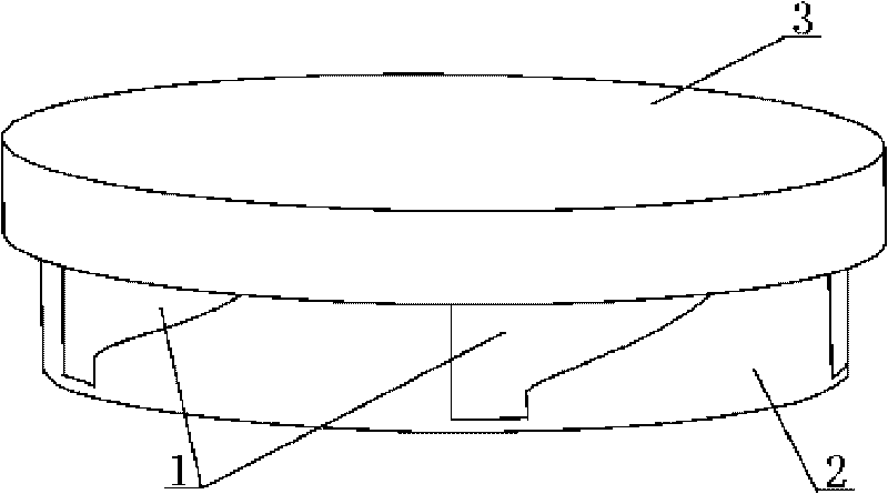
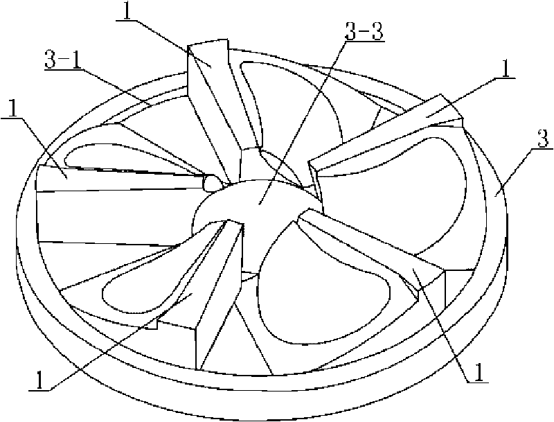
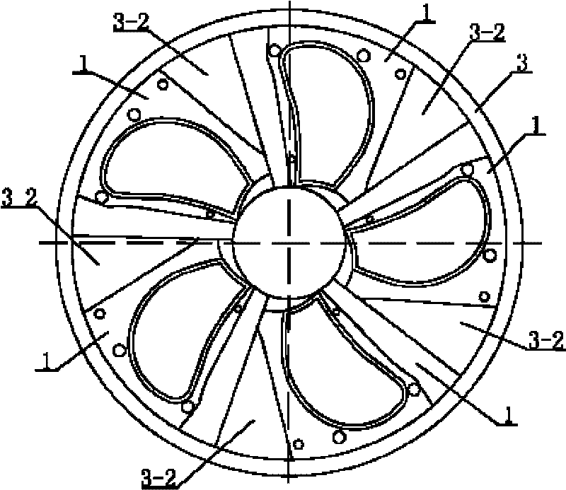
[0008] Specific implementation mode one: combine Figure 1 to Figure 7 Describe this embodiment, this embodiment is made up of at least three upper modules 1, lower mold 2 and cover plate 3, the lower end surface of cover plate 3 is provided with annular groove 3-1 along the circumference, and the inner top end surface of annular groove 3-1 At least three module slots 3-1-1 are evenly distributed on the top, the area between each module slot 3-1-1 is a positioning block 3-2, and the center of the lower end surface of the cover plate 3 is provided with a hub positioning flange 3 -3, the peripheral shape of each upper module 1 coincides with the peripheral shape of the module groove 3-1-1, and the upper mold parting surface 1 is sequentially provided on the lower end surface of each upper module 1 along the arc-shaped length direction -1 and sealing boss 1-2, upper mold parting surface 1-1 is provided with upper mold blade cavity 1-1-1, the top surface of upper mold blade cavity...

specific Embodiment approach 2

[0009] Specific implementation mode two: combination figure 1 The present embodiment is described. The upper module 1 , the cover plate 3 and the lower mold 2 of the present embodiment are all made of LY12 aluminum alloy. LY12 has good strength and compact structure, excellent processing and process performance, and is very suitable for processing components with complex surfaces such as propellers. Other components and connections are the same as those in the first embodiment.

specific Embodiment approach 3

[0010] Specific implementation mode three: combination Figure 6 ~ Figure 8 Describe this embodiment, this embodiment is realized by the following steps: Step 1, design aluminum sleeve 4-1: the outer diameter of aluminum sleeve 4-1 is smaller than the diameter of hub groove 2-3 on lower die 2 by 15~ 20mm; step 2, making the aluminum alloy propeller hub 4: wrap the unidirectional carbon fiber cloth on the outer diameter of the aluminum sleeve 4-1, and the diameter of the winding is the same as the diameter of the propeller hub slot 2-3; step 3, cutting multiple upper dies Fiber cloth and multiple lower mold fiber cloths: the fiber cloth is cut into multiple upper mold fiber cloths according to the shape of each layer in the upper mold blade cavity 1-1-1 laid on the upper module 1, and the fiber cloth is laid according to the The shape of each layer in the lower mold blade chamber 2-1-1-1 on the lower module 2-1 is cut into multiple pieces of lower mold fiber cloth; The bottom ...


PUM


Abstract

The invention relates to an integrally forming mould of a composite propeller and a manufacture method thereof, solving the problems that hubs and paddle shafting of traditional propellers vibrate, and paddle roots are easy to be damaged. In the mould, an upper mould paddle chamber is arranged on an upper mould parting curved surface, a lower mould parting curved surface that is matched with the upper-mould parting curved surface on an upper mould block is arranged on each lower mould block that is arranged on a lower mould, a lower mould paddle chamber is just opposite to the upper mould paddle chamber, each lower mould parting curved surface and seal groove on the lower mould is matched with one of the upper mould blocks, a cover plate is arranged on the upper end faces of the three upper mould blocks, and each mould block groove on the cover plate is provided with one of the upper blocks. The method comprises the following steps of: firstly, designing an aluminum sheath; secondly, manufacturing aluminum alloy hubs; thirdly, cutting pieces of upper mould fiber cloth and pieces of lower mould fiber cloth; fourthly, preparing paddles; fifthly, placing the aluminum alloy hubs; sixthly, assembling the upper and the lower moulds; seventhly, injecting epoxy resin; and eighthly, forming the mould under pressure. The invention is used for manufacturing the composite propeller.

Description

technical field [0001] The invention relates to an integral forming mold of a propeller and a manufacturing method thereof. Background technique [0002] Existing composite material propellers mostly consist of metal hubs and composite material blades. During the preparation, the composite material blade is usually formed by the bag pressure matching method or the foam plastic core filling method, and then it is connected with the propeller hub through flange flange bolts, straight shank tile connection, inverted cone type It is connected by means of connection or ear plug bolt connection. The disadvantages of the above-mentioned several preparation methods are: 1. It is difficult to achieve a good match between the metal propeller hub and the composite material propeller blade, resulting in vibration of the shafting of the propeller, and even fatigue damage at the root of the propeller; 2. Each propeller When the blade is assembled with the hub as a whole, it is easy to h...

Claims


Application Information

Patent Timeline
Patent Type & Authority Applications(China)
IPC IPC(8): B29C70/54B29C33/38B29C70/34B29K63/00B29K305/02B29K307/04B29L31/08
Inventor 赫晓东王荣国洪毅张鸿名
Owner HARBIN INST OF TECH
Why Eureka
Try Eureka