Vacuum composite heat-insulating pipeline connecting structure

A technology for connecting structures and heat-insulating pipes, which is applied in the direction of drilling pipes, casings, and drilling equipment. It can solve problems such as poor heat insulation performance, high specific gravity, and easy aging of heat-insulating bushings, and achieve simplified quantity and assembly. process, prolong the life of heat insulation, and improve the effect of heat insulation performance

Inactive Publication Date: 2010-05-12
湖北贵族真空科技股份有限公司
View PDF1 Cites 1 Cited by
  • Summary
  • Abstract
  • Description
  • Claims
  • Application Information

AI Technical Summary

Problems solved by technology

With the continuous development of heat insulation technology, the heat insulation performance of the oil pipe has been greatly improved, but the heat insulation problem of the oil pipe coupling has not been well solved, and the heat loss of the oil pipe coupling accounts for the heat loss in the oil pipe pipeline. The proportion is getting bigger and bigger
Although this patent can achieve a certain heat insulation effect, its heat insulation effect is determined by the heat insulation bushing, and the heat insulation bush is easy to age, and the heat insulation performance is not very good. Therefore, the patented oil pipe coupling The heat insulation effect is not ideal, and the heat insulation effect is difficult to maintain for a long time

Method used


Image

  • Vacuum composite heat-insulating pipeline connecting structure
  • Vacuum composite heat-insulating pipeline connecting structure

Examples


Embodiment Construction

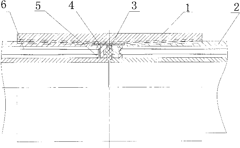
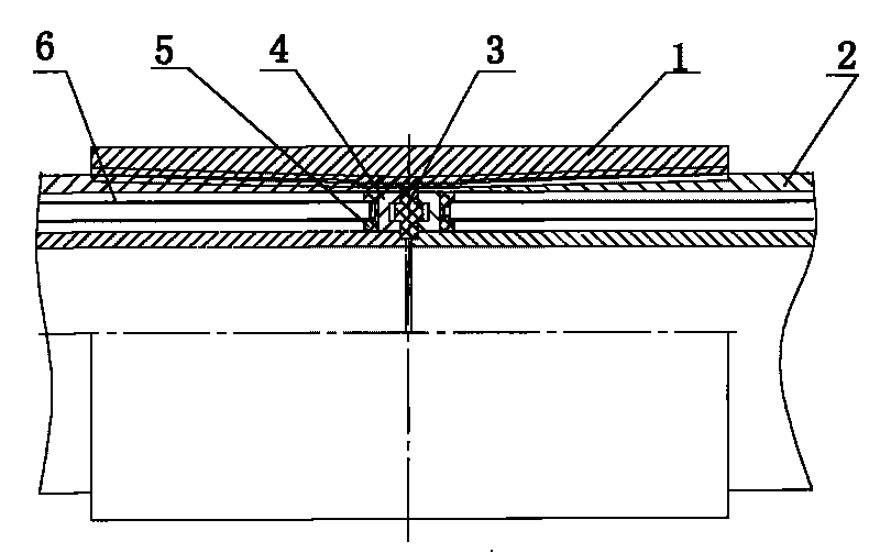
[0011] This embodiment is composed of a vacuum composite heat insulation pipe 2, a coupling 1 and a sealing gasket 3. The coupling 1 is a metal pipe. Both ends of the inner hole of the coupling are taper holes with a large outer diameter and a smaller inner diameter. The connection part of the two vacuum composite heat insulation pipes 2 is connected, and the outer surface of the connection part of the vacuum composite heat insulation pipe is a threaded conical surface that matches with the threaded conical hole at either end of the inner hole of the coupling, and the end of the vacuum composite heat insulation pipe 2 is welded There is a sealing plug 4, and one or more rings of grooves are arranged on the outer end surface of the sealing plug 4, and one ring of grooves is arranged in this embodiment.

[0012] The vacuum composite heat insulation pipe 2 is composed of an inner pipe and an outer pipe. A double-layer evacuated pipe 6 is arranged between the inner and outer pipes. Th...


PUM


Abstract

The invention discloses a vacuum composite heat-insulating pipeline connecting structure, which comprises vacuum composite heat-insulating pipes, a coupler and a gland bush, wherein the coupler is a tubular structure; the two ends of an inner hole of the coupler are provided with threaded tapered holes respectively of which outer ends are greater while inner ends are smaller and which are connected with connecting parts of the two adjacent vacuum composite heat-insulating pipes respectively; the outer surface of the connecting part of the vacuum composite heat-insulating pipe is a threaded tapered surface matched with the threaded tapered hole at any end of the inner hole of the coupler; the end face of the vacuum composite heat-insulating pipe is provided with at least one circle of groove along a circumferential direction; and the gland bush is arranged in the groove between the end faces of the two vacuum composite heat-insulating pipes. The vacuum composite heat-insulating pipeline connecting structure can greatly improve heat-insulating property at junctions of the pipeline, prolong the heat-insulating service life of the pipeline, reduce the number of pipeline connecting parts and simplify the assembly process of the pipeline connecting parts, and is especially applied to the coupling of underground oil pipes for steam injection and oil extraction.

Description

Technical field [0001] The invention relates to oil pipes, in particular to a vacuum composite heat insulation pipe connection structure, which is suitable for the connection of heat preservation liquid and gas transportation pipes, and is particularly suitable for the connection of downhole oil pipes for steam injection and oil extraction of heavy oil. Background technique [0002] The currently used tubing is generally installed in the well of several thousand meters. Due to the depth of the well, the thick oil, the large temperature difference in downhole heat transfer, and the small thermal resistance of the steel pipe, the heavy oil in the tubing loses heat during the process of transporting the heavy oil from downhole to the ground Therefore, this kind of oil pipe and coupling must adopt heat-insulating oil pipe and heat-insulating coupling with superior heat insulation performance. With the continuous development of thermal insulation technology, the thermal insulation per...

Claims


Application Information

Patent Timeline
Patent Type & Authority Applications(China)
IPC IPC(8): E21B17/02
Inventor 白明军吴平张琰周生宣
Owner 湖北贵族真空科技股份有限公司
Why Eureka
Try Eureka