Device for testing flow of lubricating oil nozzle of engine

A technology of lubricating oil nozzle and flow test, which is used in engine testing, measuring device, liquid/fluid solid measurement, etc., can solve problems such as poor compatibility, adjustment of oil receiving cups that cannot be telescopically rotated, affecting test accuracy, etc. The effect of reducing labor intensity

Inactive Publication Date: 2010-05-12
SHENYANG LIMING AERO-ENGINE GROUP CORPORATION
View PDF0 Cites 15 Cited by
  • Summary
  • Abstract
  • Description
  • Claims
  • Application Information

AI Technical Summary

Problems solved by technology

[0002] At present, there is no special device for removing the dissolved air in the lubricating oil in the domestic aero-engine lubricating oil contact device test equipment, which causes a lot of oil foam during the test process, which seriously affects the accuracy of the test; and for t

Method used


Image

  • Device for testing flow of lubricating oil nozzle of engine
  • Device for testing flow of lubricating oil nozzle of engine
  • Device for testing flow of lubricating oil nozzle of engine

Examples


Embodiment Construction

[0016] The detailed structure of an engine lubricating oil nozzle flow test device of the present invention will be described in conjunction with embodiments and accompanying drawings.

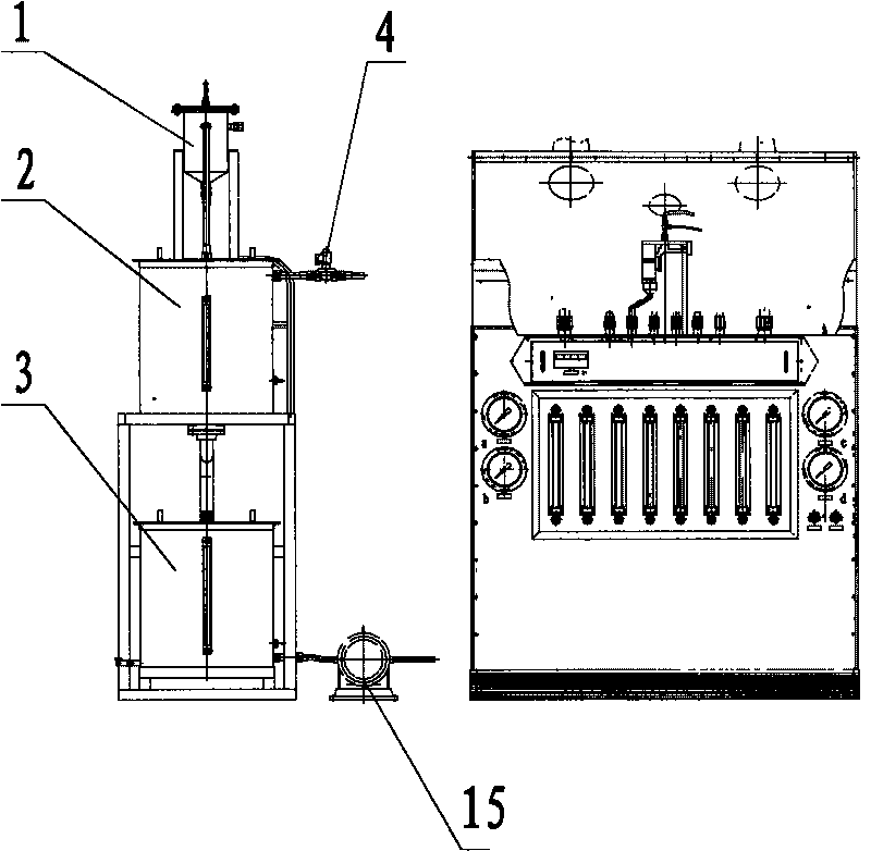
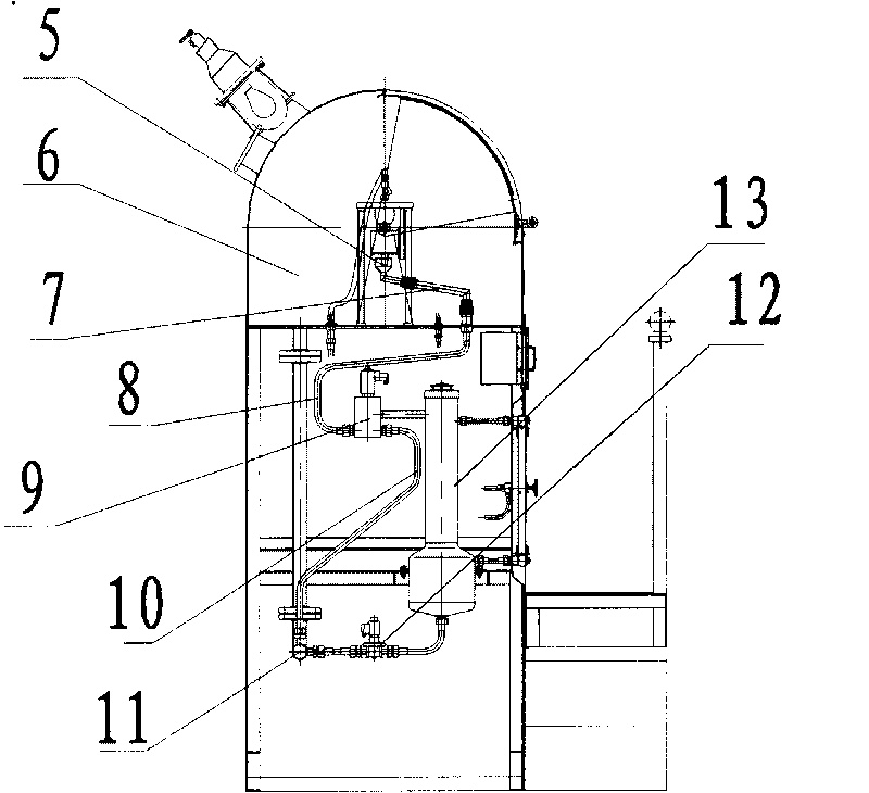
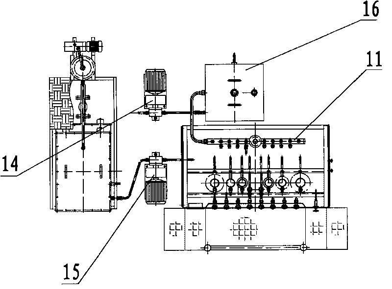
[0017] The device includes an oil receiving cup 5, a first transfer pipe 7, a second transfer pipe 8, a third transfer pipe 10, a working chamber 6, an oil return tank 16, an oil collection pipe 11, a two-position three-way solenoid valve 9, and a metering oil cup 13. The first electromagnetic valve 4, the second electromagnetic valve 12, the oil return pump 14, the oil supply pump 15 and the combination oil tank, wherein the combination oil tank includes the oil collector 1, the vacuum oil tank 2, the consumption oil tank 3, the third electromagnetic valve 17, the fourth Solenoid valve 18, vacuum pump 19.

[0018] The connection of the device is: the oil collector 1 in the combined oil tank is connected to the vacuum pump 19, the oil collector 1 is located on the upper part of the vacuum oil ...


PUM


Abstract

The invention relates to a device for testing the flow of a lubricating oil nozzle of an engine, belonging to the technical field of space shuttle engines. The device comprises an oil receiving cup, a first switching pipe, a second switching pipe, a third switching pipe, a working room, an oil return tank, an oil collecting pipe, a two-position three-way electromagnetic valve, an oil metering cup, a first electromagnetic valve, a second electromagnetic valve, an oil return pump, an oil supply pump and a combined oil tank, wherein the combined oil tank comprises an oil collector, a vacuum oil tank, a consumption oil tank, a third electromagnetic valve, a fourth electromagnetic valve and a vacuum pump. With the structure of a vacuum combined split oil tank, the device can remove air dissolved in lubricating oil. An upper and a lower split oil tanks are used, wherein the lower oil tank is used for supplying oil, and the upper vacuum oil tank is used for removing the dissolved air. For the compatibility of different types of nozzles, the designed oil receiving cup can flex and rotate according to different oil receiving distances and angles, can be used for testing different types of nozzles and reduce the labor intensity of workers.

Description

technical field [0001] The invention belongs to the technical field of aircraft engines, and in particular relates to an engine lubricating oil nozzle flow test device. Background technique [0002] At present, there is no special device for removing the dissolved air in the lubricating oil in the domestic aero-engine lubricating oil contact device test equipment, which causes a lot of oil foam during the test process, which seriously affects the accuracy of the test; and for the current various types of nozzles in the installation Since the oil receiving cup cannot be adjusted for stretching and rotating according to the different angles of the oil receiving distance when receiving oil, it cannot be tested for different types of nozzles, and the compatibility is poor. Contents of the invention [0003] Aiming at the deficiencies in the prior art, the present invention provides an engine lubricating oil nozzle flow test device. By adding a combined oil tank and an adjustab...

Claims


Application Information

Patent Timeline
IPC IPC(8): G01M15/00G01M15/02G01F19/00
Inventor 李辛郭旭刘玫龚弋飞迟艳宋伟
Owner SHENYANG LIMING AERO-ENGINE GROUP CORPORATION
Why Eureka
Try Eureka