Rigidity testing device of fixed type metal sheet stamping part

A metal sheet and testing device technology, applied in the direction of testing the hardness of materials, etc., can solve the problems of inability to guarantee accuracy, non-standardization, scientificity, and no fixed stiffness testing device for sheet metal stamping parts, etc., to achieve compact structure, work Efficiency improvement, reasonable design effect

Inactive Publication Date: 2010-05-12
HARBIN INST OF TECH
View PDF0 Cites 20 Cited by
  • Summary
  • Abstract
  • Description
  • Claims
  • Application Information

AI Technical Summary

Problems solved by technology

Judging the stiffness of automobile panels in this way does not meet the requirements of standardization and scientificity, let alone guarantee the accuracy
At present, the research on the stiffness test of large sheet metal stamping parts is only limited to the anti-concave stiffness, and there is no fixed stiffness testing device for sheet metal stamping parts.

Method used


Image

  • Rigidity testing device of fixed type metal sheet stamping part
  • Rigidity testing device of fixed type metal sheet stamping part
  • Rigidity testing device of fixed type metal sheet stamping part

Examples


specific Embodiment approach 1

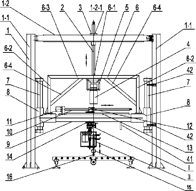
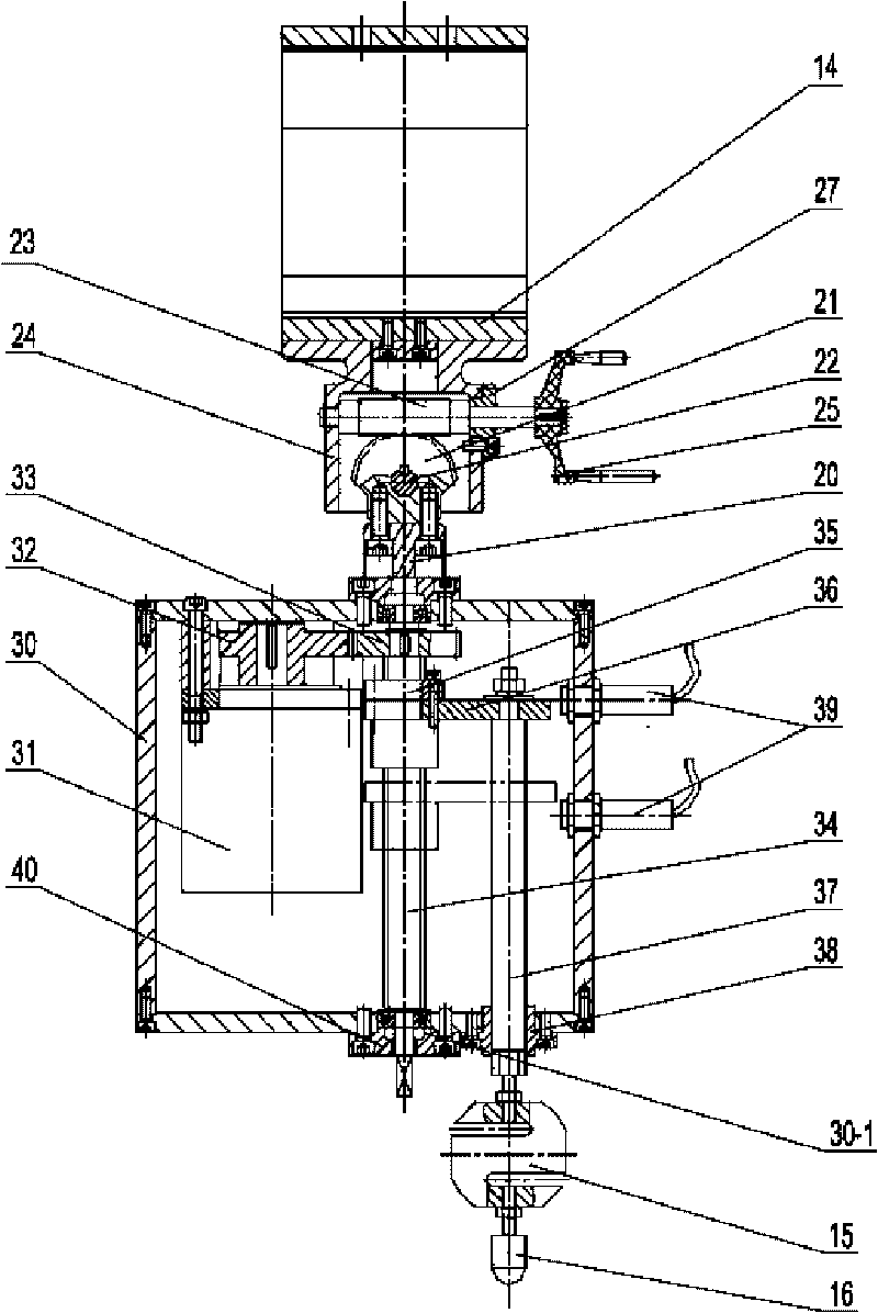
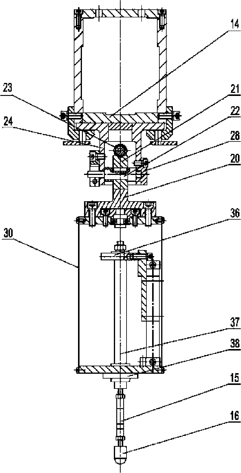
[0007] Specific implementation mode one: as Figure 1~3 As shown, the fixed sheet metal stamping parts rigidity testing device in this embodiment includes a frame 1, a first lead screw 2, a first screw nut 3, a first motor 4, a motor seat 5, a bracket 6, and two guide posts 7 , two tee sleeves 8, beam tube 9, second lead screw 10, second motor 11, second nut 12, guide rail 13, support slide 14, worm gear mechanism I, fine-tuning loading mechanism assembly II, A pressure sensor 15 and a pressure head 16, a first through hole 1-2-1 is opened on the beam 1-2 of the frame 1, and the first thread nut 3 is arranged in the first through hole 1 of the beam 1-2 - In 2-1, the upper part of the first lead screw 2 is screwed to the first screw nut 3, and the lower end of the first lead screw 2 passes through the second through hole 6-1 of the bracket 6 and connects with the first motor 4 The output shaft of the frame 1 is affixed, and the upper part of the bracket 6 is affixed to the fir...

specific Embodiment approach 2

[0008] Specific implementation mode two: as figure 1 As shown, the rack 1 in this embodiment is composed of two columns 1-1 and a beam 1-2, and the upper ends of the two columns 1-1 are connected together by the beam 1-2. With such a design, the frame 1 has a simple structure, high rigidity and good stability. Other components and connections are the same as those in the first embodiment.

specific Embodiment approach 3

[0009] Specific implementation mode three: as figure 1 As shown, the bracket 6 in this embodiment is composed of two pillars 6-2, a horizontal frame 6-3 and two reinforcing ribs 6-4, and the upper ends of the two pillars 6-2 are connected by a horizontal frame 6-3 Together, one end of each reinforcing rib 6-4 is fixed on the horizontal frame 6-3, and the other end of each reinforcing rib 6-4 is fixed on the corresponding pillar 6-2, and the horizontal frame 6-3 The middle part has the second through hole 6-1. With such a design, the support 6 has a large bearing capacity, good rigidity, and negligibly small deformation during loading. Other compositions and connections are the same as those in Embodiment 1 or 2.


PUM


Abstract

The invention relates to a rigidity testing device of a fixed type metal sheet stamping part, relating to a rigidity testing device and solving the problem that no rigidity testing device of the fixed type metal sheet stamping part exists at present. One end of a second screw is fixedly connected with an output shaft of a second motor and parallelly arranged above a beam pipe; the lower end surface of a guide rail is fixed on the upper end surface of the beam pipe arranged below the second screw; a supporting sliding seat is arranged on the beam pipe and connected with the guide rail slilably; a second nut is arranged on the second screw and fixed on the upper end surface of the supporting sliding seat; the upper end surface of a worm and gear mechanism is fixed on the lower end surface of the supporting sliding seat; the upper end surface of a fine-adjustment loading mechanism assembly is fixed on a worm connecting seat of the worm and gear mechanism; the upper end of a pressure sensor is fixedly connected with the lower end surface of a guide rod of the fine-adjustment loading mechanism assembly; and a press head is fixed on the lower end surface of the pressure sensor. The invention can realize movement or rotation with multiple freedom degrees by the press head of the rigidity testing device and accurately measure the rigidity of the metal sheet stamping part.

Description

technical field [0001] The invention relates to a rigidity testing device for metal sheet stamping parts, in particular to a rigidity testing device for fixed automobile covering parts. Background technique [0002] Most of the automobile cover parts are large sheet metal stamping parts. The relative thickness of the sheet metal stamping parts, that is, the ratio of the plate thickness to the maximum outline size of the part is very small, and the stiffness of the sheet metal stamping parts is relatively poor. Therefore, the inspection of the automobile cover parts before leaving the factory Work is especially important. The scale of my country's auto industry is relatively large, but the foundation is relatively poor, especially the testing equipment is relatively backward. When domestic automobile manufacturers measure and compare the stiffness of panel panels, they generally rely on experienced professionals to press the panel panel with their hands to feel the force app...

Claims


Application Information

Patent Timeline
Patent Type & Authority Applications(China)
IPC IPC(8): G01N3/42
Inventor 张晓辉邢忠文杨洪亮雷呈喜赵立红
Owner HARBIN INST OF TECH
Why Eureka
Try Eureka