Automobile disk-type braking method and device based on motor drive

A disc brake, motor-driven technology, applied in the direction of brake transmission, brakes, vehicle components, etc., can solve the problems of high price and complex structure, and achieve the effect of low cost, simple and compact structure, and good versatility

Inactive Publication Date: 2010-05-19
CHERY AUTOMOBILE CO LTD
View PDF3 Cites 5 Cited by
  • Summary
  • Abstract
  • Description
  • Claims
  • Application Information

AI Technical Summary

Problems solved by technology

[0003] The prior art most relevant to the present invention is the disc type electric energy brake of Siemens Company and the disc type electric energy brake of Continental TEVES Company, but the motor of the aforementioned brake needs to be customized, and there are disadvantages such as complex structure and high price.

Method used


Image

  • Automobile disk-type braking method and device based on motor drive
  • Automobile disk-type braking method and device based on motor drive

Examples


Embodiment Construction

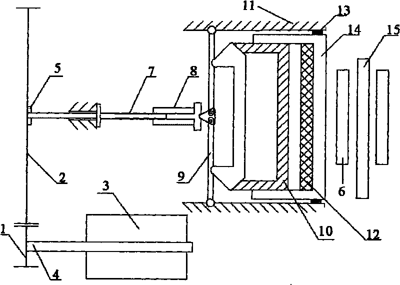
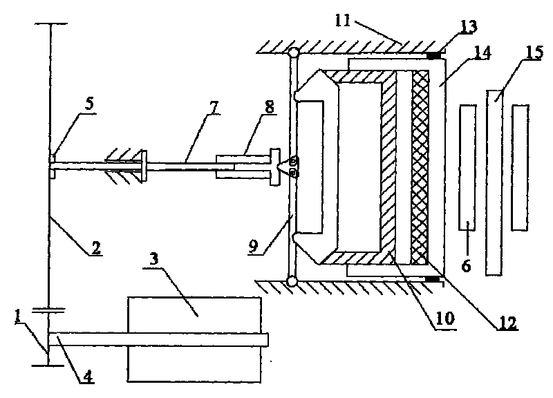
[0019] As shown in the figure, the brake includes a brake piston 14, a brake block 6, and a brake disc 15. The brake piston 14 can push the brake block 6 to press the brake disc 15, which is the prior art.

[0020] The power output shaft 4 of the 12V DC brushless motor 3 is equipped with a driving gear 1, and the driven gear 2 meshes with the driving gear. The transmission ratio of the driving gear 1 and the driven gear 2 is 1:40; the driven gear 2 passes through the spline 5 Connected with the screw rod 7, there is a nut 8 matched with the screw rod, the nut 8 is connected to the end of the booster lever 9, a transmission sleeve 10 is arranged between the booster lever 9 and the brake piston 14, and the booster lever 9 passes through The transmission sleeve 10 drives the brake piston 14 to move. A pressure sensor 12 is installed inside the brake piston, which is used to measure the output braking torque and realize precise control of braking. A return rubber ring 13 is provi...


PUM


Abstract

The invention relates to an automobile disk-type braking method and a device based on motor drive. The device has simple structure and can realize larger motor output force gain. The invention has the technical scheme that power output by the motor drives a braking piston to move after boosted by two stages of a gear engaging mechanism and a boosting lever, so that a braking block tightly presses a braking disc to brake automobiles.

Description

technical field [0001] The invention relates to an automobile disc brake method and device driven by a motor. Background technique [0002] At present, the braking system adopted by most automobiles at home and abroad is still based on hydraulic control of mechanical pressure to achieve the purpose of braking. Due to the disadvantages of traditional hydraulic brakes such as complex structure, many parts, space occupation, inconvenient layout and poor system scalability, etc. At present, many automotive electronics suppliers are developing electromechanical braking systems, also known as BBW (brake-by-wire) in English. Electromechanical braking technology refers to using the motor as the power source of the system, using a purely mechanical mechanism to achieve motion conversion and force increase, and finally realize the compression of brake pads and brake discs, and then generate the required braking force. [0003] The prior art most relevant to the present invention is ...

Claims


Application Information

Patent Timeline
IPC IPC(8): B60T13/74
Inventor 朱得亚
Owner CHERY AUTOMOBILE CO LTD
Why Eureka
Try Eureka