Horizontal shell and tube type condenser with liquid guide devices

A shell-and-tube condenser technology that is applied to steam/steam condensers, heat exchanger shells, lighting and heating equipment, etc. Problems such as the increase in the volume of thermal equipment, to achieve the effect of reducing the thickness of the liquid film, simple installation, and avoiding the increase of the thickness of the liquid film

Inactive Publication Date: 2010-05-19
张吉礼
View PDF0 Cites 9 Cited by
  • Summary
  • Abstract
  • Description
  • Claims
  • Application Information

AI Technical Summary

Problems solved by technology

However, these works did not solve the problem that the condensate in the upper row of tubes in the horizontal shell-and-tube condenser drips down, which causes the liquid film of the lower row of heat exchange tubes to thicken, resulting in a decrease in the overall heat transfer performance of the tube bundle (called the tube bundle eff

Method used


Image

  • Horizontal shell and tube type condenser with liquid guide devices
  • Horizontal shell and tube type condenser with liquid guide devices
  • Horizontal shell and tube type condenser with liquid guide devices

Examples


Embodiment 1

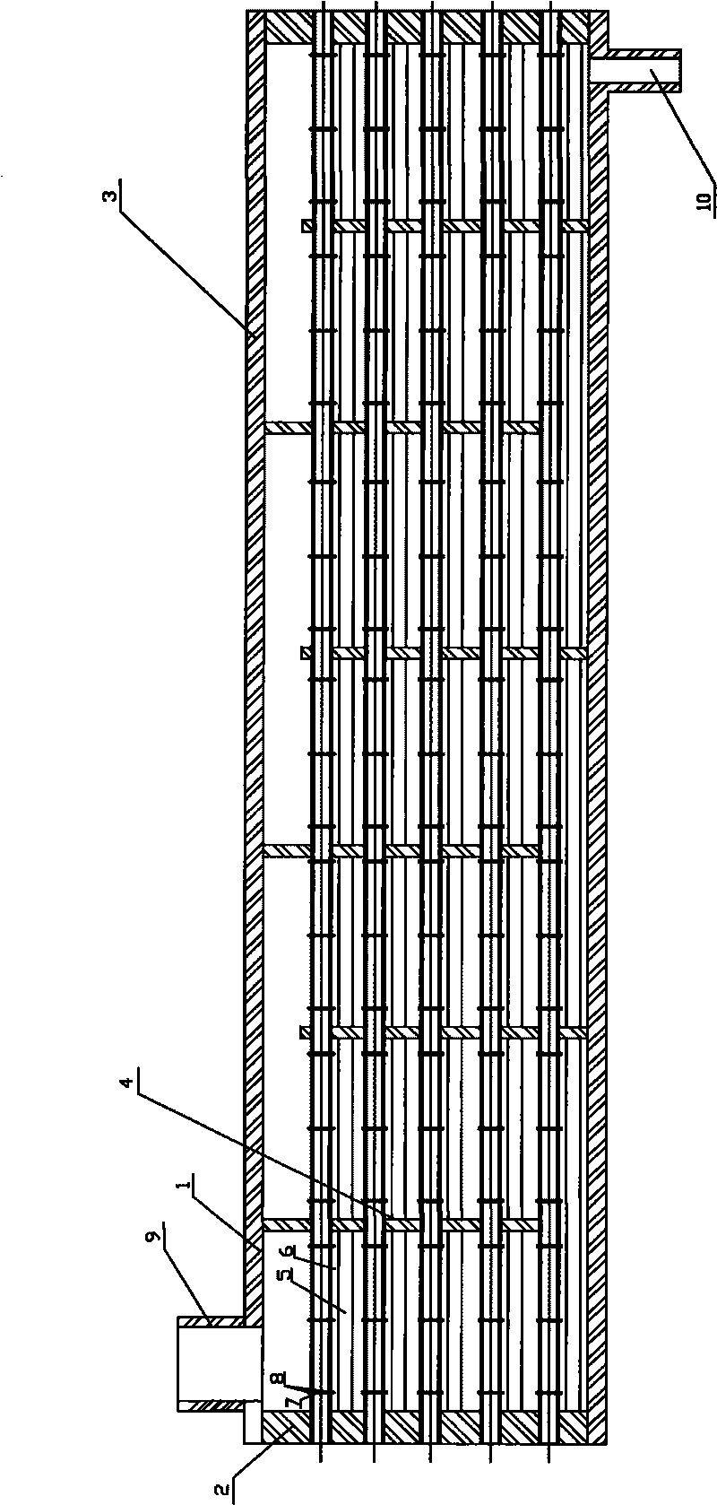
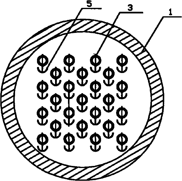
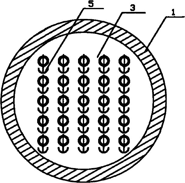
[0042] A horizontal shell-and-tube condenser with a liquid guide, its composition includes: a shell 1, the two sides of the shell are connected to the tube plate 2, and the shell space enclosed by the shell and the tube plate A set of heat exchange tubes 3 are installed, the heat exchange tubes are equipped with a support plate 4, a continuous liquid guide 5 is installed under the heat exchange tubes, and an air inlet 9 and an outlet are opened on the shell. Liquid port 10.

Embodiment 2

[0044] A horizontal shell-and-tube condenser with a liquid guide, its composition includes: a shell 1, the two sides of the shell are connected to the tube plate 2, and the shell space enclosed by the shell and the tube plate A set of heat exchange tubes 3 are installed, the heat exchange tubes are equipped with a support plate 4, a continuous liquid guide 5 is installed under the heat exchange tubes, and an air inlet 9 and an outlet are opened on the shell. Liquid port 10.

[0045] In the horizontal shell-and-tube condenser with a liquid guide, a continuous flow guide plate 6 is included between the heat exchange tube and the liquid guide.

Embodiment 3

[0047] A horizontal shell-and-tube condenser with a liquid guide, its composition includes: a shell 1, the two sides of the shell are connected to the tube plate 2, and the shell space enclosed by the shell and the tube plate A set of heat exchange tubes 3 are installed, the heat exchange tubes are equipped with a support plate 4, a continuous liquid guide 5 is installed under the heat exchange tubes, and an air inlet 9 and an outlet are opened on the shell. Liquid port 10.

[0048] In the horizontal shell-and-tube condenser with a liquid guide, a continuous flow guide plate 6 is included between the heat exchange tube and the liquid guide.

[0049] The horizontal shell-and-tube condenser with a liquid guide, the liquid guide is a liquid collection type liquid guide, its section shape is a single arc, and the liquid guide is along the length of the heat exchange tube The direction has a bump towards one end.

[0050] In the horizontal shell-and-tube condenser with a liquid g...


PUM


Abstract

The invention relates to a horizontal shell and tube type condenser with liquid guide devices. At present, when designing the horizontal shell and tube type condenser, people compensate the negative influence of tube bundle effect on the condensation heat exchange only by increasing the amount of heat exchange tubes so as to cause increase of the volume of heat-exchange equipment and the improvement of the production cost. The horizontal shell and tube type condenser with the liquid guide devices comprises a shell (1). Both sides of the shell are connected with a tube plate (2). A space inside the shell surrounded by the shell and the tube plate is provided with a set of heat exchange tubes (3). The heat exchange tubes are provided with support plates (4). Continuous liquid guide devices (5) are installed below the heat exchange tube and are collection liquid guide device or separation liquid guide devices. The shell is provided with an air inlet (9) and a liquid outlet (10). The invention can be widely applied in the fields of petroleum, chemical industry, metallurgy, pharmaceutical manufacturing, air conditioning, refrigeration, heat supply and the like.

Description

Technical field: [0001] The invention relates to a horizontal shell and tube condenser, in particular to a horizontal shell and tube condenser with a liquid guide. Background technique: [0002] Horizontal shell and tube condensers are widely used in petroleum, chemical industry, metallurgy, pharmaceutical, air conditioning, refrigeration and heating and other fields. The heat exchange efficiency directly affects the industrial production cost and energy utilization efficiency, so it has always been an important Research and improve objects. Since the 1970s, in order to improve the heat transfer performance of condensing heat exchangers, people have achieved a lot of fruitful results by changing the structural characteristics of the outer surface of the tube. However, these works have not solved the problem that the condensate in the upper row of tubes drips down in the horizontal shell and tube condenser, which causes the liquid film of the lower row of heat exchange tubes...

Claims


Application Information

Patent Timeline
IPC IPC(8): F28B1/00F28F9/00F28F13/04
Inventor 张吉礼马志先
Owner 张吉礼
Why Eureka
Try Eureka