Method for inhibiting moving-gimbal effects of single gimbal magnetically suspended control moment gyroscope

A technology for controlling torque gyroscopes and magnetic levitation, which can be used in rotating gyroscopes, space navigation aircraft guidance devices, etc., and can solve the problems of not completely suppressing stability and accuracy.

Inactive Publication Date: 2010-05-19
BEIHANG UNIV
View PDF3 Cites 12 Cited by
  • Summary
  • Abstract
  • Description
  • Claims
  • Application Information

AI Technical Summary

Problems solved by technology

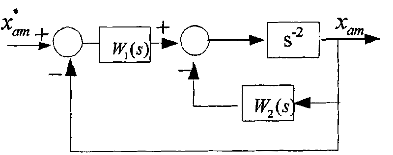
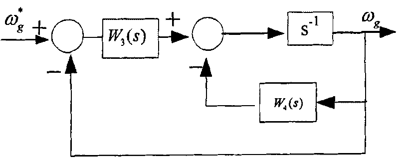
[0004] The technical problem of the present invention is: to overcome the deficiency that the angular rate feedforward control cannot completely suppress the influence of the dynamic frame effect on the stability and precision of the single-frame magnetic levitation CMG, and propose a method for suppressing the single-frame magnetic levitation CMG dynamic frame effect, In the r

Method used


Image

  • Method for inhibiting moving-gimbal effects of single gimbal magnetically suspended control moment gyroscope
  • Method for inhibiting moving-gimbal effects of single gimbal magnetically suspended control moment gyroscope
  • Method for inhibiting moving-gimbal effects of single gimbal magnetically suspended control moment gyroscope

Examples


Embodiment Construction

[0067] specific implementation plan

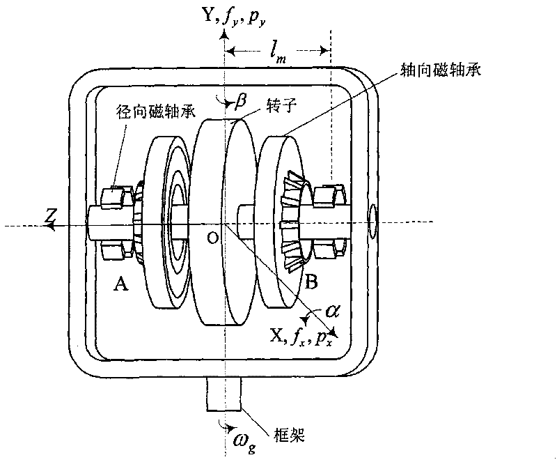
[0068] The implementation object of the present invention is as image 3 As shown, the rotor is suspended by two radial magnetic bearings and two axial magnetic bearings, which are called A-end radial magnetic bearings, B-end radial magnetic bearings, A-end axial magnetic bearings, and B-end axial magnetic bearings. , A, B end windings along X, Y directions respectively form radial ax, bx, ay, by channels, rotor windings along Z direction form axial z channels, and the frame axis is perpendicular to the rotor axis. Specific embodiments of the present invention are as Figure 5 As shown, the specific implementation steps are as follows:

[0069] 1. According to Newton's second law and the gyro technical equation, the state equation of the maglev CMG is established when the base is stationary:

[0070] X · = f ...


PUM


Abstract

The invention relates to a method for inhibiting moving-gimbal effects of a single gimbal magnetically suspended control moment gyroscope. In the method, a state equation of the single gimbal magnetically suspended control moment gyroscope is set up according to newton second law and a gyro technique equation; an inversion analysis of a system is calculated by utilizing an inverse system method; in a rotor system, moving-gimbal displacement of a magnetically suspended rotor is eliminated through state feedback of rotor displacement, an rotor reflection angular speed and a gimbal angular speed, and in a gimbal system, reactionary torque interference of the rotor to the gimbal system is eliminated through state feedback of the gimbal angular speed and the rotor reflection angular speed; and a robust servocontrol strategy is adopted to improve the robustness of the whole system. In the method, the moving-gimbal displacement of the magnetically suspended rotor is eliminated, the reactionary torque interference of the rotor system to the gimbal system is also eliminated in the gimbal moving process, and the stability and precision of the whole single gimbal magnetically suspended control moment gyroscope are improved. The method belongs to the technical field of aerospace control, and can be applied to high-precision control of magnetically suspended control moment gyroscopes.

Description

technical field [0001] The invention relates to a method for suppressing the dynamic frame effect of a single-frame magnetic suspension control moment gyro (Control Moment Gyroscope-CMG), which is suitable for high-precision control of the single-frame magnetic suspension control CMG. technical background [0002] CMG is the key actuator for attitude control of spacecraft such as space stations, large satellites, agile maneuvering satellites and space maneuvering platforms. The CMG consists of a constant-speed rotor and a frame rate servo system. When the frame rotates, the angular momentum of the rotor is forced to change, and the gyro torque is output outward. The CMG output torque is proportional to the angular momentum of its high-speed rotor. Spacecraft attitude actuators are required to have the characteristics of long life, large torque, high precision, small size, and low power consumption. Because of these advantages, magnetic levitation CMG has become an important...

Claims


Application Information

Patent Timeline
IPC IPC(8): G01C19/24B64G1/28
Inventor 房建成任元孙津济霍甲徐向波马纪军汤恩琼
Owner BEIHANG UNIV
Why Eureka
Try Eureka