Signal demodulating method for inhibiting vibration error of fiber optic gyro

A technology of vibration error and signal demodulation, which is applied in the field of eliminating measurement error caused by vibration and suppressing vibration error of interference fiber optic gyroscope, can solve problems such as measurement result error, eliminate constant value drift error, and improve measurement accuracy Effect

Inactive Publication Date: 2010-05-19
HARBIN ENG UNIV
View PDF0 Cites 21 Cited by
  • Summary
  • Abstract
  • Description
  • Claims
  • Application Information

AI Technical Summary

Problems solved by technology

Since the gyro is used to measure the attitude angle and angular velocity of the carrier, it needs to be fixed to the carrier, so the measurement results will be affected by the vibration of the carrier and cause errors

Method used


Image

  • Signal demodulating method for inhibiting vibration error of fiber optic gyro
  • Signal demodulating method for inhibiting vibration error of fiber optic gyro
  • Signal demodulating method for inhibiting vibration error of fiber optic gyro

Examples


Embodiment Construction

[0013] The present invention will be further described in detail below in conjunction with the accompanying drawings.

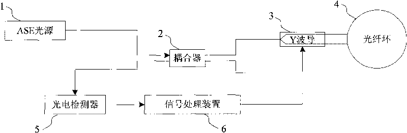
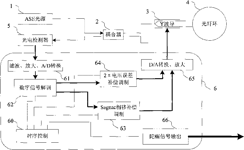
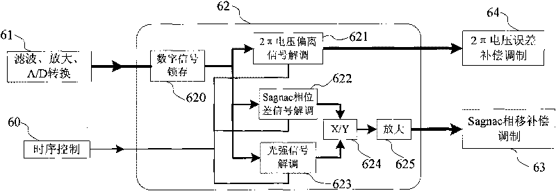
[0014] exist Figure 1-3 Middle: 1. ASE light source 2. Coupler 3. Y waveguide 4. Optical fiber ring 5. Photoelectric detector 6. Signal processor 60. Timing control module 61. Filtering, amplification, A / D conversion module 62. Digital signal processing module 63. Sagnac phase shift compensation signal modulation module 64. 2π voltage error compensation modulation module 65. D / A conversion and amplification module 66. Filter gyro signal output module 620. Digital signal latch module 621. 2π voltage deviation signal demodulation module 622. Sagnac Phase difference signal demodulation module 623. Light intensity signal demodulation module 624. Division module 625. Amplification module.

[0015] The demodulation method for suppressing the vibration error signal of the fiber optic gyroscope according to the present invention belongs to a part of the structural ...


PUM


Abstract

The invention provides a signal demodulating method for inhibiting a vibration error of a fiber optic gyro. After a system is powered on, light power signals detected by a photoelectric detector in real time are subjected to filtration, amplification and an A / D converter to form digital signals; the digital signals are latched by a digital latch module; and the latched light power digital singles are demodulated to form Sagnac phase difference signals, 2pi voltage deviation signals and light power signals; the demodulated Sagnac phase difference signals are divided by the light power signals to obtain new demodulated signals which are amplified and output to a Sagnac phase deviation compensation modulation module; the demodulated 2pi voltage deviation signals are output to a 2pi voltage error compensation modulation module; and then the modulated signals of Sagnac phase deviation compensation signals and 2pi voltage error compensation modulation signals are fed back to a gyro closed loop. In the method, a constant drift error of the gyro and partial additional noise error caused by vibration are eliminated, and the measuring accuracy of the gyro in vibration environment is improved.

Description

(1) Technical field [0001] The invention relates to the field of optical fiber sensing in optoelectronic technology, in particular to a method for suppressing the vibration error of an interference type optical fiber gyroscope. More specifically, it is a method of eliminating measurement errors caused by vibrations through signal demodulation. (2) Background technology [0002] Fiber optic gyro is an instrument for measuring angular velocity, which is composed of light source 1, coupler 2, Y waveguide 3, fiber optic ring 4, photoelectric detector 5 and signal processing device 6 and other hardware. The signal processing device 6 includes a timing control module 60, filtering, amplification, A / D conversion module 61, digital signal demodulation module 62, Sagnac phase shift compensation modulation module 63, 2π voltage error compensation modulation module 64, D / A The conversion and amplification module 65, and the gyro signal output module 66, and the interference fiber opti...

Claims


Application Information

Patent Timeline
Patent Type & Authority Applications(China)
IPC IPC(8): G01C19/72
Inventor 吴磊舒建涛李绪友张瑞鹏左文龙孙枫程建华孙巧英周广涛徐博
Owner HARBIN ENG UNIV
Why Eureka
Try Eureka