Permanent magnet speed controller

A technology of permanent magnet speed governor and regulator, which is applied in the direction of asynchronous induction clutch/brake, etc., can solve the problems of small adjustment range, large volume, large push-pull mechanism, etc., and achieve high power density, high output power, and structure simple effect

Active Publication Date: 2010-05-19
南京艾凌节能技术有限公司
View PDF5 Cites 33 Cited by
  • Summary
  • Abstract
  • Description
  • Claims
  • Application Information

AI Technical Summary

Problems solved by technology

[0004] 1 Complex structure and large volume
[0005] 2 It cannot be applied to systems with large axial movement
The uniformity of the air gap on both sides of the adjustable magnetic coupler is very high. If the air gap on both sides is uneven, it will generate axial additional load, which will affect the life of the transmission system be

Method used


Image

  • Permanent magnet speed controller
  • Permanent magnet speed controller
  • Permanent magnet speed controller

Examples


Embodiment Construction

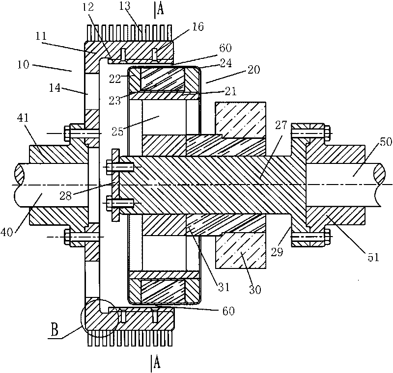
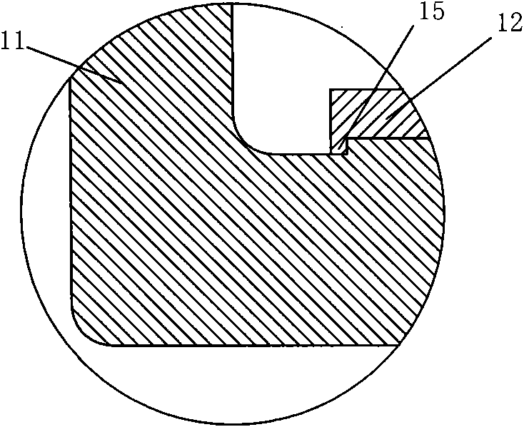
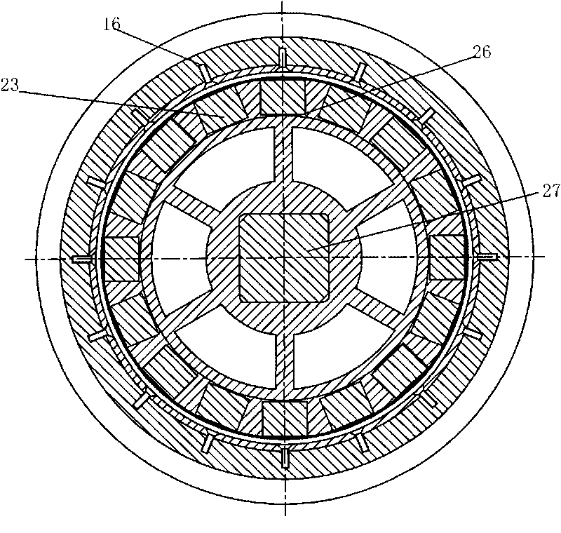
[0021] Refer to attached Figure 1~4 :

[0022] The input shaft 40 and the output shaft 50 are coaxial, and the cylindrical conductor rotor 10 is mounted on the input shaft 40 through a flange 41 . Cylindrical conductor rotor body 11 is equipped with cylindrical conductor 12 made of non-magnetic conductive material, and the end 15 of cylindrical conductor 12 is preferably extruded and embedded by spinning method. The cylindrical conductor rotor body 11, or the cylindrical conductor member 12 is assembled to the cylindrical conductor rotor body 11 with screws 16. A ventilation hole 14 is provided at the bottom of the cylindrical conductor rotor body 11; a heat dissipation device 13 is provided on its outer circular surface, and the heat dissipation device 13 can be made of a material with high thermal conductivity; the heat dissipation device 13 can be a ring piece by welding or embedding Assembled on the cylindrical conductor rotor body 11, can also be assembled on the cylin...


PUM


Abstract

The invention discloses a permanent magnet speed controller, which comprises a cylindrical conductor rotor, a cylindrical permanent magnet rotor and a controller, and is characterized in that: the cylindrical permanent magnet rotor is arranged in the cylindrical conductor rotor; the cylindrical permanent magnet rotor and the cylindrical conductor rotor are separated by an air gap therebetween, and rotate independently along respective rotating shafts; and the controller controls relative positions of the cylindrical conductor rotor and the cylindrical permanent magnet rotor so as to change the action area between the cylindrical permanent magnet rotor and the cylindrical conductor rotor and change the transmission torque between the cylindrical permanent magnet rotor and the cylindrical conductor rotor. Permanent magnets of the permanent magnet speed controller are arranged on an outer ring of the cylindrical permanent magnet rotor, and output power and torque higher than those of a common permanent magnet speed controller can be obtained; the moving direction of the cylindrical permanent magnet rotor on the shaft thereof is vertical to that of the magnetic force of the permanent magnets, and the controller for controlling the movement of the cylindrical permanent magnet rotor only needs small driving force; and axial additional loads are not generated nearly in the adjustment, and the permanent magnet speed controller can be well applied to transmission systems with large axial running number.

Description

technical field [0001] The invention relates to a speed regulating device, in particular to a permanent magnet speed regulating device. Background technique [0002] The patent number is 98802726.7, the authorized announcement number is CN 1140042C, and the authorized announcement date is an invention patent on February 25, 2004, which discloses an adjustable magnetic coupler. It comprises: first and second rotating shafts having axes of rotation; two coaxial magnetic rotors each comprising a corresponding set of permanent magnets; two coaxial conductor rotors each having a nonferrous conductive ring, said nonferrous The conductive ring is separated from a corresponding one of said sets of stickers by an air gap; the two said conductor rotors are separated by a fixed axial distance and are mounted as a unit on said first rotating shaft to rotate therewith the two said magnetic rotors are then mounted to move axially in opposite directions relative to said second axis of rot...

Claims


Application Information

Patent Timeline
IPC IPC(8): H02K49/04
Inventor 不公告发明人
Owner 南京艾凌节能技术有限公司
Why Eureka
Try Eureka