Spiral sludge dewatering equipment with collapsable shaft

A sludge dewatering machine and stacked screw technology, which is applied in the direction of dehydration/drying/concentrated sludge treatment, etc., can solve the problems of reducing the service life of movable plates, and achieve the effects of increasing service life, reducing pressure and improving dehydration efficiency

Inactive Publication Date: 2010-05-26
SHANGHAI TECHASE ENVIRONMENT PROTECTION
View PDF0 Cites 27 Cited by
  • Summary
  • Abstract
  • Description
  • Claims
  • Application Information

AI Technical Summary

Problems solved by technology

However, according to practical experience, if the lead angle of the screw device is reduced, the wear of the movable plate acting

Method used


Image

  • Spiral sludge dewatering equipment with collapsable shaft
  • Spiral sludge dewatering equipment with collapsable shaft
  • Spiral sludge dewatering equipment with collapsable shaft

Examples


Embodiment Construction

[0012] The screw stacking sludge dewatering machine of the present invention will be further described in detail below in conjunction with the accompanying drawings.

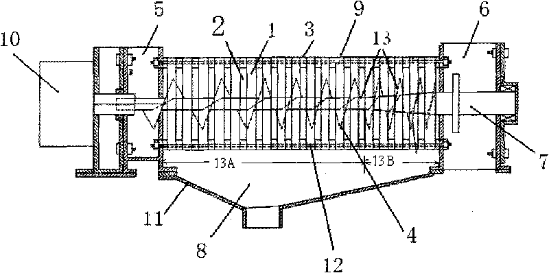
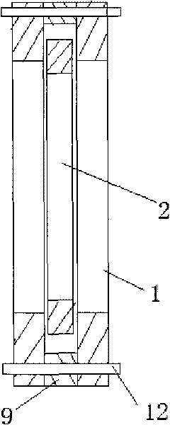
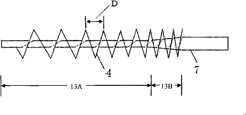
[0013] like figure 1 Shown is a schematic structural view of the screw stacking sludge dehydrator of the present invention, a screw stacking sludge dewatering machine using a variable diameter shaft, including a housing 11, a fixed plate 1, a movable plate 2 and a screw shaft 7 and a structure. The filter body 3, the filtrate recovery device 8, the mud feeding box 5 and the mud discharging box 6, several annular fixing plates 1 are arranged in sequence inside the shell 11, and a concentric and movable An annular movable plate 2, a filtrate recovery device 8 is provided at the bottom of the filter body 3; the screw shaft 7 runs through the interior of the fixed plate 1 and the movable plate 2, and the mud feeding box 5 and the mud discharging box 6 are respectively arranged at both ends of the screw shaft 7 The ...


PUM


Abstract

The invention discloses a spiral sludge dewatering equipment with a collapsable shaft. The inside of a shell is provided with a plurality of annular fixed plates and annular movable plates which are mutually alternate and are concentric; a spiral shaft runs through the inside of each of the annular fixed plates and the annular movable plates to form a filtration body; a sludge feeding box and a sludge discharge box are arranged at both ends of the spiral shaft respectively so as to ensure that the sludge is dehydrated under the compression action of the filtration body and then enters the sludge discharge box; and a filtrate flows out from the gaps between the fixed plates and the movable plates during the operation. By designing that the screw pitch of the spiral shaft is gradually reduced and the diameter of the spiral shaft begins to be gradually increased at certain specific position along the direction of the sludge discharge box, and setting a lead angle to be between 13.5 and 14.5 DEG at the same time, the dehydration efficiency of the sludge is improved, the damage caused by the overlarge pressure on the movable plates during the treatment caused by the overlarge lead angle is also avoided, and the service life of the movable plates is prolonged.

Description

technical field [0001] The invention relates to a sludge dehydrator. Background technique [0002] The stacked screw type sludge dehydrator of the prior art can be widely used in the following fields: (1) organic sludge produced in waste water treatment processes such as pig farm waste water and food processing waste water; (2) electroplating waste water, printing and dyeing waste water, containing Inorganic sludge produced in the process of waste water treatment such as cutting oil waste water and paint waste water; (3) Separating liquid from vegetable residues, fruit peels, food residues and other processing objects. Relying on this type of dehydrator, through the rotary motion of the screw device, the movable plate and the fixed plate move relative to each other, and at the same time clean the gaps in the filter part to prevent clogging. [0003] For this type of sludge dewatering machine, in order to improve the dehydration efficiency of sludge, it is necessary to reduc...

Claims


Application Information

Patent Timeline
IPC IPC(8): C02F11/12
Inventor 张文标张亚雷刘道广司慧萍田建强梁松波
Owner SHANGHAI TECHASE ENVIRONMENT PROTECTION
Why Eureka
Try Eureka