Engine using glow plug resistance for estimating combustion temperature

A combustion temperature, glow plug technology, applied in engine ignition, engine control, engine components, etc., can solve expensive and other problems

Inactive Publication Date: 2010-05-26
GM GLOBAL TECH OPERATIONS LLC
View PDF0 Cites 4 Cited by
  • Summary
  • Abstract
  • Description
  • Claims
  • Application Information

AI Technical Summary

Problems solved by technology

Placing temperature sensors in or close to the combustion chamber is a known method of sensing combustion temperature, but is an expensive solution
Also, regression or model-ba

Method used


Image

  • Engine using glow plug resistance for estimating combustion temperature
  • Engine using glow plug resistance for estimating combustion temperature
  • Engine using glow plug resistance for estimating combustion temperature

Examples


Embodiment Construction

[0018] The following description is merely exemplary in nature and is not intended to limit the invention, application or uses.

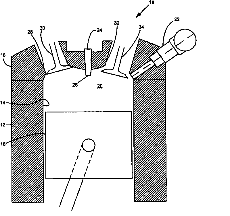
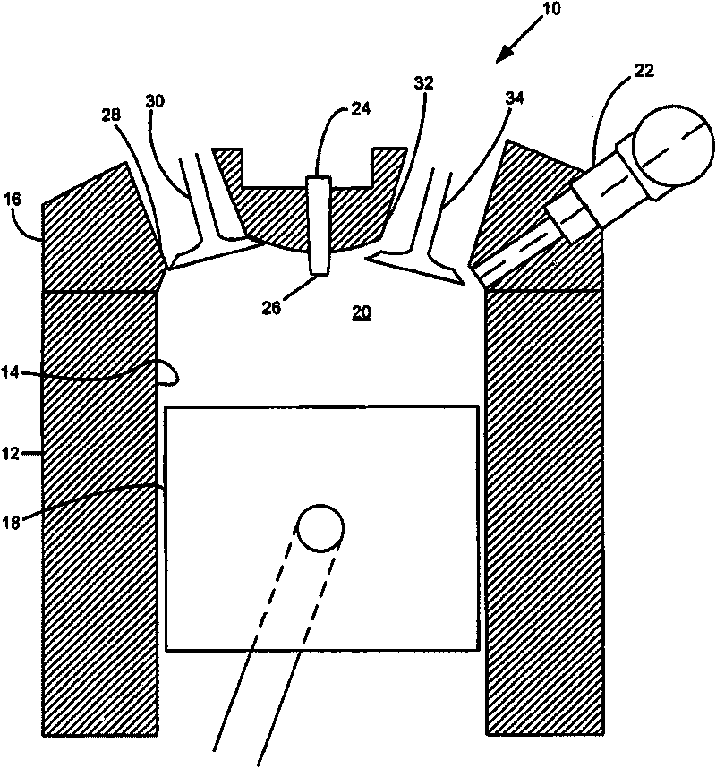
[0019] refer to figure 1 , showing an exemplary diesel engine with a glow plug disposed within the combustion chamber. Specifically, diesel engine 10 has a cylinder block 12 defining at least one cylinder 14 enclosed by a cylinder head 16 . It should be understood that a typical engine includes a plurality of cylinders 14 . Piston 18 reciprocates within cylinder 14 and, with cylinder head 16 , forms combustion chamber 20 . Cylinder head 16 is fitted with injection nozzles or injectors 22 that inject fuel into combustion chamber 20 for compression ignition therein. The cylinder head is also fitted with a glow plug 24 of known form having a heat emitting tip 26 extending into the combustion chamber 20 . Heat generating tip 26 is heated during cold engine start and low temperature operation to help ignite fuel injected into combustion chamber 20 du...


PUM


Abstract

The present invention relates to an engine using glow plug resistance for estimating combustion temperature. More specifically, the invention discloses an internal combustion engine that includes an engine block defining at least one cylinder therein. A cylinder head is attached to the engine block and defines a combustion chamber with the at least one cylinder in the engine block. A piston is disposed within the at least one cylinder. A glow plug is disposed within the combustion chamber. A resistance of the glow plug is detected and an estimated combustion temperature is determined based upon the detected resistance of the glow plug. The engine is then controlled based upon the estimated combustion temperature established from the glow plug resistance.

Description

technical field [0001] The present invention relates to internal combustion engines, and more particularly to engines using glow plug resistance to estimate combustion temperature. Background technique [0002] The statements in this section merely provide background information related to the present disclosure and may not constitute prior art. [0003] In theory, diesel and gasoline engines are very similar. They are both internal combustion engines designed to convert the chemical energy available in the fuel into mechanical energy. This mechanical energy moves the piston up and down inside the cylinder. The pistons are connected to the crankshaft, and the up and down motion of the pistons, which is known as linear motion, causes the rotational motion needed to turn the wheels of the car. [0004] Both diesel and gasoline engines convert fuel into energy through a series of small deflagrations, or combustions. The main difference between diesel and gasoline engines is...

Claims


Application Information

Patent Timeline
IPC IPC(8): F02D41/30
CPCF02D35/02F02P19/025F02P19/028F02D35/026
Inventor Q·马
Owner GM GLOBAL TECH OPERATIONS LLC
Why Eureka
Try Eureka