Air-conditioning heat pump device

A heat pump device and air conditioner technology, applied in the field of air conditioner heat pump devices, can solve the problems of high exhaust temperature of compressor, increase in gas content, increase in throttling loss of throttling mechanism, etc., and achieve the effects of reliable operation, simple structure and low cost

Inactive Publication Date: 2010-05-26
刘雄
View PDF1 Cites 23 Cited by
  • Summary
  • Abstract
  • Description
  • Claims
  • Application Information

AI Technical Summary

Problems solved by technology

[0003] 1) When the condensing temperature is too high or the evaporation temperature is too low, the throttling loss of the throttling mechanism will increase, resulting in an increase in the gas content in the gas-liquid two-phase mixture after throttling, so that the heat exchange capacity of the evaporator cannot be fully utilized , so as to reduce the efficiency of the heat pump device, on the other hand, it will cause the exhaust temperature of the compressor to be too high, and in severe cases, it will affect the normal operation of the compressor;
[0004] 2) When realizing the function of simultaneously cooling and producing domestic hot water according to the user's needs in summer, the above-mentioned device needs to control the heat supply and cooling capacity at the same time according to the user's requirements, or simultaneously control the temperature of the cooled medium (such as : indoor air temperature or chilled water temperature) and the temperature of the heated medium (for example: domestic hot water temperature), therefore, when the above device adopts single-stage compression, due to the mutual influence between the heat supply and cooling capacity, at the same time The control of the heat supply and cooling capacity, or the temperature of the cooled medium and the temperature of the heated medium cannot be very precise;

Method used


Image

  • Air-conditioning heat pump device
  • Air-conditioning heat pump device
  • Air-conditioning heat pump device

Examples


Embodiment 1

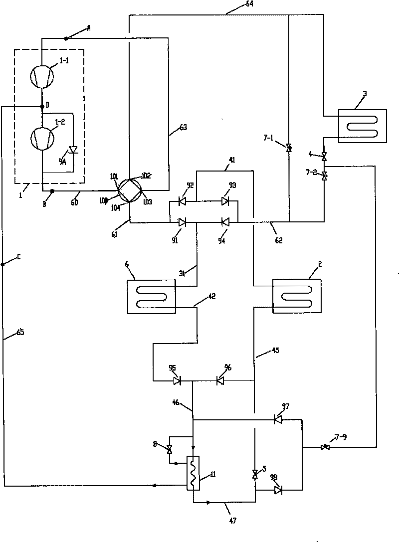
[0034] Such as figure 1 As shown, the whole device includes the following components: compression mechanism 1, heat source side heat exchanger 2, user side heat exchanger 3, second heat exchanger 6, first throttling mechanism 4, second throttling mechanism 5, four Through valve 100, first flow control valve 7-1, second flow control valve 7-2, ninth flow control valve 7-9, third throttling mechanism 8, economizer 11, first one-way valve 91, second Two one-way valves 92, the third one-way valve 93, the fourth one-way valve 94, the fifth one-way valve 95, the sixth one-way valve 96, the seventh one-way valve 97 and the eighth one-way valve 98;

[0035] The four-way valve 100 is provided with four connection nodes: 101, 102, 103, 104, each connection node is connected to two internal channels;

[0036] The compression mechanism 1 has three gas connection ports, namely: the first suction port A, the second suction port C, and the exhaust port B; Machine 1-2, the ninth one-way val...

Embodiment 2

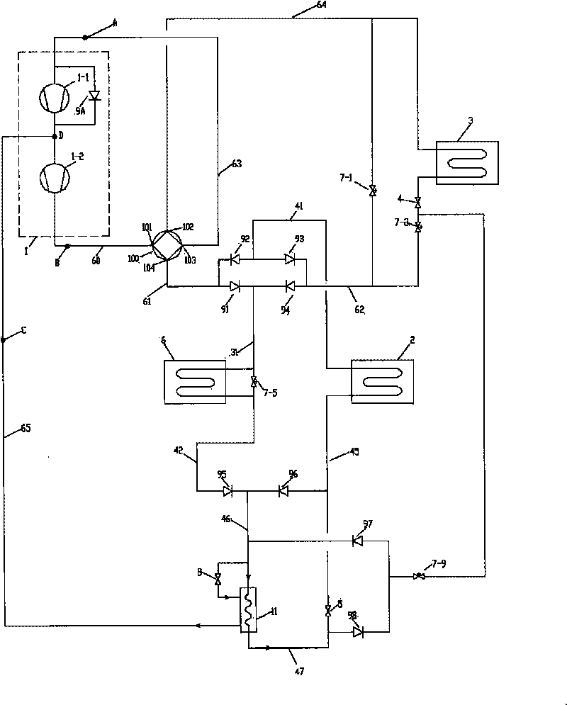
[0116] Such as figure 2 As shown, the technical solution of the compression mechanism 1 adopted in embodiment 1 also has the following variations:

[0117] The inlet port of the low-pressure compressor 1-1 is connected to the first suction port A, and the outlet port of the low-pressure compressor 1-1 passes through the inlet port of the high-pressure compressor 1-2, the outlet port of the high-pressure compressor 1-2, and the discharge port successively. The air port B is connected, the inlet port of the ninth one-way valve 9A is connected with the pipeline between the inlet port of the low-pressure compressor 1-1 and the first suction port A, and the outlet port of the ninth one-way valve 9A is connected with the low-pressure compressor 1-1. The outlet end of -1 is connected to the pipeline between the inlet end of the high-pressure compressor 1-2, and the second air suction port C is connected to the air supply port D of the compression mechanism 1;

[0118] The air suppl...

Embodiment 3

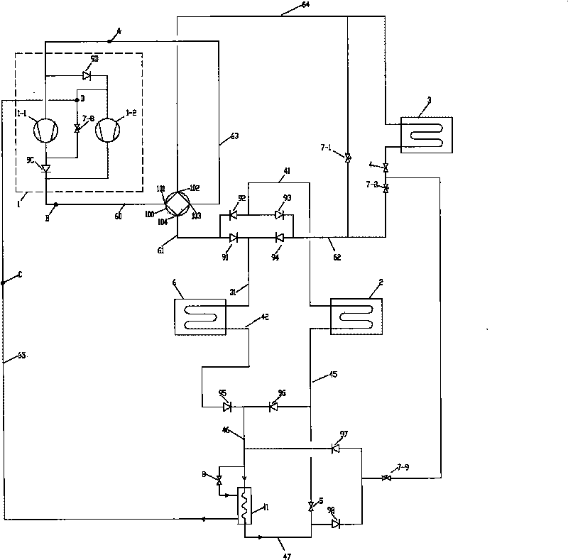
[0121] image 3 As shown, the difference between it and Embodiment 1 is that the compression mechanism 1 adopts a different technical solution, and other parts in the system are exactly the same as Embodiment 1. The compression mechanism 1 is composed of a low-pressure compressor 1-1, a high-pressure compressor 1-2, an eleventh one-way valve 9C, a twelfth one-way valve 9D, and an eighth flow control valve 7-8.

[0122]The connection scheme is as follows: the inlet port of the low-pressure compressor 1-1 is connected to the first suction port A, and the outlet port of the low-pressure compressor 1-1 passes through the inlet port of the eleventh one-way valve 9C, the eleventh one-way valve The outlet port of 9C is connected with the exhaust port B, the inlet port of the twelfth one-way valve 9D is connected with the pipeline between the first suction port A and the inlet port of the low-pressure compressor 1-1, and the outlet port of the twelfth one-way valve 9D The inlet port ...


PUM


Abstract

The invention discloses an air-conditioning heat pump device, which comprises a compressing mechanism, a heat-source side heat exchanger, a user side heat exchanger, a second heat exchanger, a second throttling mechanism, a four-way valve, a first flow-direction control valve, a second flow-direction control valve, a ninth flow-direction control valve, a first one-way valve, a second one-way valve, a third one-way valve, a fourth-one-way valve, an economizer, a third throttling mechanism, a fifty one-way valve, a sixth one-way valve, a seventh one-way valve and an eighth one-way valve. When in operation, free switching of single-double stage compression can be realized according to requirements; the air-conditioning heat pump device can work normally under high-low temperature working environment to realize a plurality of operation states, such as producing domestic hot water, refrigerating or heating, and the like. The invention has the advantages of simple structure, reliable operation, and low cost, and is particularly suitable for domestic small-medium size air-conditioning heat pump devices with domestic hot water requirements.

Description

technical field [0001] The invention relates to an air-conditioning heat pump device, which belongs to the technical field of air-conditioning and refrigeration. Background technique [0002] The invention patent with the application number 200710305376.3 relates to a dual-purpose heat pump device for winter and summer. During the operation of the device throughout the year, it can realize cooling, heating, production of domestic hot water, and recovery of condensation heat during cooling. It needs multiple functions such as cooling and production of domestic hot water at the same time, heating and production of domestic hot water at the same time according to user needs in winter; but the above-mentioned device has the following defects during operation: [0003] 1) When the condensing temperature is too high or the evaporation temperature is too low, the throttling loss of the throttling mechanism will increase, resulting in an increase in the gas content in the gas-liquid...

Claims


Application Information

Patent Timeline
Patent Type & Authority Applications(China)
IPC IPC(8): F25B29/00F25B31/00F25B41/04
Inventor 刘雄
Owner 刘雄
Why Eureka
Try Eureka