Electric vacuum cleaner
A vacuum cleaner, electric technology, applied in the direction of vacuum cleaners, electric components, electrical components, etc., to achieve the effect of low price
- Summary
- Abstract
- Description
- Claims
- Application Information
AI Technical Summary
Problems solved by technology
Method used
Image

Examples
Embodiment 1
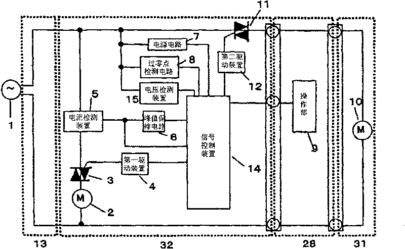
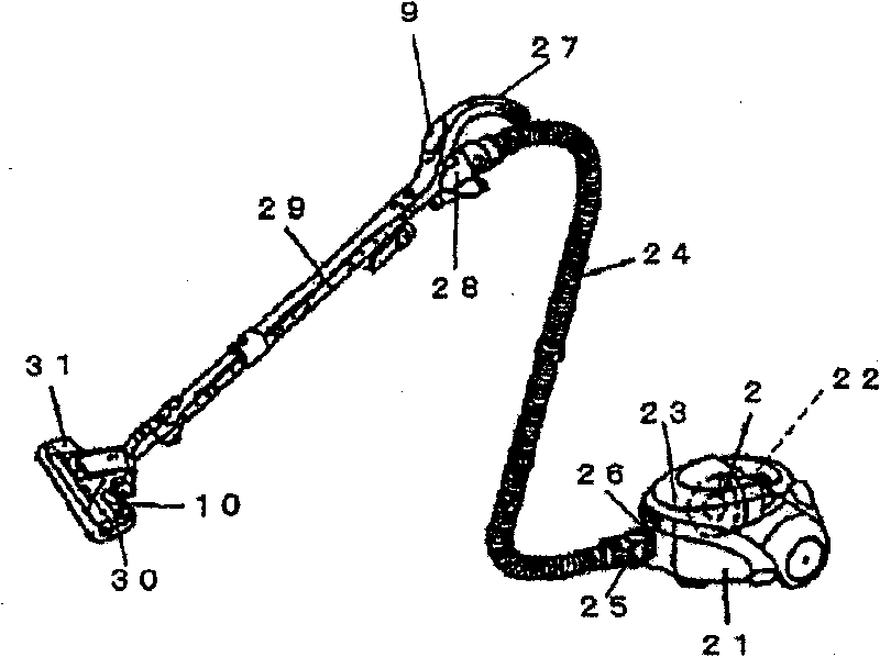
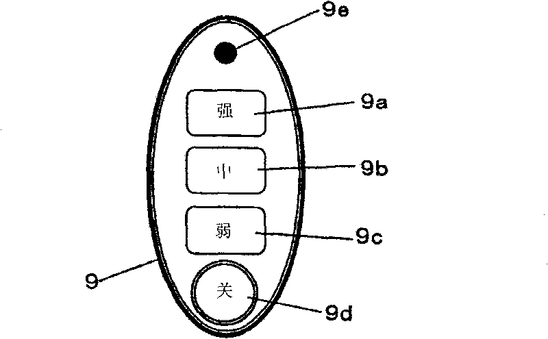
[0031] first pass Figure 1 to Figure 4 The electric vacuum cleaner in the first embodiment of the present invention will be described. figure 2 It is an overall perspective view of the electric vacuum cleaner in this embodiment. exist figure 2 Among them, the rear portion of the vacuum cleaner body 21 is provided with an electric blower chamber 22, in which an electric blower 2 is arranged. The front portion of the vacuum cleaner body 21 is provided with a dust collection chamber 23 for catching dust. In addition, the front end of the vacuum cleaner body 21 is provided with a suction port 26, and a connecting pipe 25 provided on one end of the hose 24 is connected to the suction port 26 in a detachable manner. At the other end of the hose 24 there is a front end tube 28 which is gripped during vacuuming and also has a handle 27 . The handle 27 is provided with an operating part 9 for operating the vacuum cleaner body 21. 29 is a freely telescopic extension tube, and one...
Embodiment 2
[0040] Refer below Figure 7 The control process of the electric vacuum cleaner in the second embodiment of the present invention will be described. The overall structure of the electric vacuum cleaner in this embodiment is the same as that of Embodiment 1, and the structure of the control circuit only removes the voltage detection device 15 from Embodiment 1, so a detailed description thereof is omitted here.
[0041] During the electric fan 2 is driven, the signal control device 14 always outputs 1ms to the trigger pulse ( Figure 5 The output value of the current detection device 5 after the ▲ time t3=1ms) is monitored. If the output value of the above-mentioned current detection device 5 is less than 1V, the signal control device 14 judges as "half-wave loss", accumulates the number of times judged as "half-wave loss", and uses this accumulated value every second to detect abnormality. Judgment of electric sparks and control after abnormal electric sparks are confirmed. ...
Embodiment 3
[0046] Refer below Figure 8 The control procedure of the electric vacuum cleaner in the third embodiment of the present invention will be described. The overall structure of the electric vacuum cleaner in this embodiment is the same as that of Embodiment 1, and the structure of the control circuit only excludes the voltage detection device 15 from Embodiment 1, so a detailed description thereof is omitted here.
[0047] During the electric fan 2 is driven, the signal control device 14 always outputs 1ms to the trigger pulse ( Figure 5▲After time t3=1ms), the output value of the current detection device 5 is monitored. If the output value of the above-mentioned current detection device 5 is less than 1.3V, the signal control device 14 judges as "voltage drop", and counts up the number of times. In addition, when the output value of the above-mentioned current detection device 5 is less than 1V, it is judged as "half-wave loss", the number of judgments as "half-wave loss" is...
PUM
 Abstract
Description
Claims
Application Information
 - R&D
- Intellectual Property
- Life Sciences
- Materials
- Tech Scout
- Unparalleled Data Quality
- Higher Quality Content
- 60% Fewer Hallucinations
Browse by: Latest US Patents, China's latest patents, Technical Efficacy Thesaurus, Application Domain, Technology Topic, Popular Technical Reports.
© 2025 PatSnap. All rights reserved.Legal|Privacy policy|Modern Slavery Act Transparency Statement|Sitemap|About US| Contact US: help@patsnap.com