Automobile power-driven automatic expanding footboard

An automatic retractable and pedal technology, which is applied to the layout of pedals or ladders, vehicle parts, transportation and packaging, etc., can solve the problems of rusty chains, large movement resistance, complicated manufacturing process, and high maintenance costs, so as to reduce noise sources, The effect of simplifying the processing process and reducing the processing cost

Inactive Publication Date: 2010-06-02
JIANGXI JIANGLING MOTORS GRP REFITTED VEHICLES CO LTD
View PDF5 Cites 7 Cited by
  • Summary
  • Abstract
  • Description
  • Claims
  • Application Information

AI Technical Summary

Problems solved by technology

[0002] At present, telescopic pedals are installed on large and medium-sized passenger cars and commercial vehicles. The most commonly used is to use DC12v / DC24v DC motors as (as) power, output power through the DC motor, and transmit it to the driven wheel through the chain. A bracket is installed on one side of the chain. The connection form between the bracket and the pedal board surface achieves the power transmission effect of the pedal's automatic expansion and contraction. The electrical control adopts the method of 3 relays and the stroke switch. Closed) to achieve the effect of automatic expansion and contraction of the pedal. The transmission mechanism adopts chain transmission. Due to the influence of external factors and other factors, the movement resistance of the chain is rusted and the pinning movement is large. The production process is complicated, the maintenance cost is high, and the appearance is affected.

Method used


Image

  • Automobile power-driven automatic expanding footboard
  • Automobile power-driven automatic expanding footboard

Examples


Embodiment Construction

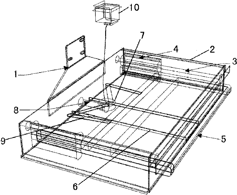
[0008] like figure 1 As shown, the present invention is realized in this way, it comprises support 1, support frame 2, slide bar 3, linear bearing 4, pedal 5, installation beam 6, motor 7, connecting rod 8, scissors type transmission rod 9, anti-collision The controller 10 is characterized in that the bracket 1 is connected to the support frame 2, and the inner walls on both sides of the support frame 2 are respectively connected with a slide bar 3, and the slide bar 3 is covered with a linear bearing 4, and one end of the linear bearing 4 is fixedly connected to the end of the pedal 5, and the support frame 2 The middle part of the bottom end is connected with a mounting beam 6, and a motor 7 is installed on the mounting beam 6, and the motor 7 is supported by a connecting rod 8. The motor 7 is symmetrically connected to a pair of scissor transmission rods 9 through the driven teeth of the gearbox, and the scissor transmission rod 9 is connected The pedal 5 and the motor 7 ar...


PUM


Abstract

The invention relates to an automobile power-driven automatic expanding footboard which is characterized in that: a bracket is connected with a supporting frame, the inner walls at two sides of the supporting frame are respectively connected with sliding rods, a linear bearing is sheathed on the sliding rod, one end of the linear bearing is fixedly connected at the end of the footboard, a mounting beam is connected in the middle part of the bottom end of the supporting frame, a motor is arranged on the mounting beam and is supported by a connecting rod, the motor is connected with a pair of shearing-type driving levels symmetrically by a drive gear of a gear box, the shearing-type driving levels are connected with the footboard, and the motor is connected with an anti-collision controller. The automobile power-driven automatic expanding footboard has the advantages tat: 1. motor output teeth are adopted to transmit to driven gears of the gear box, and the driven gear output teeth drive two arms to do two-way expansion movement, so as to form force along the same direction and achieve the expanding mechanical effect; 2. long-distance linear movement function in a small space can be realized, the sliding rods are tightly matched with a linear bearing clearance, so as to reduce the noise resource when the automobile body bumps; in addition, the processing manufacturability of the sliding rods and the linear bearing can be improved, the processing procedure is simplified and the processing cost is reduced.

Description

technical field [0001] The invention relates to an automobile pedal, in particular to an automobile electric automatic retractable pedal. Background technique [0002] At present, telescopic pedals are installed on large and medium-sized passenger cars and commercial vehicles. The most commonly used is to use DC12v / DC24v DC motors as (as) power, output power through the DC motor, and transmit it to the driven wheel through the chain. A bracket is installed on one side of the chain. The connection form between the bracket and the pedal board surface achieves the power transmission effect of the pedal's automatic expansion and contraction. The electrical control adopts the method of 3 relays and the stroke switch. Closed) to achieve the effect of automatic expansion and contraction of the pedal. The transmission mechanism adopts chain transmission. Due to the influence of factors such as the outside world, the chain is rusted and the pinning movement resistance is large. The m...

Claims


Application Information

Patent Timeline
Patent Type & Authority Applications(China)
IPC IPC(8): B60R3/02
Inventor 刘存宾饶良星宋宏伟邹志强黄学良黄新磊
Owner JIANGXI JIANGLING MOTORS GRP REFITTED VEHICLES CO LTD
Why Eureka
Try Eureka