Depth indicator

A technology of depth indicator and indicator, which is used in elevators, lifting equipment in mines, transportation and packaging, etc., can solve the problems of difficult gearbox processing, inconvenient assembly and maintenance, and complex structure, and achieve outstanding economic benefits. , the effect of reducing manufacturing difficulty and simplifying structure

Inactive Publication Date: 2010-06-02
湖南金三星煤机制造有限公司
View PDF0 Cites 4 Cited by
  • Summary
  • Abstract
  • Description
  • Claims
  • Application Information

AI Technical Summary

Problems solved by technology

This technical solution has a complex structure, especially the gearbox with worm gear is difficult to process, high in cost, and inconvenient to assemble and maintain

Method used


Image

  • Depth indicator
  • Depth indicator
  • Depth indicator

Examples


Embodiment 1

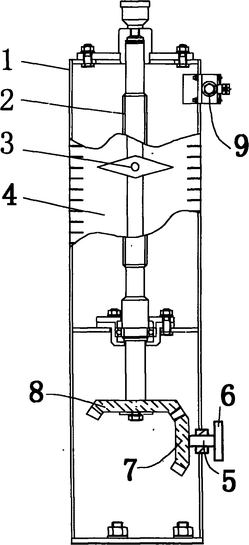
[0020] figure 1 Shown is a depth indicator, comprising a frame 1, and a rotatable screw 2 vertically installed on the frame 1, an indicator 3 is installed on the screw 2, a scale bar 4 is installed on the frame 1, and is movably connected to the machine frame. Transverse axis 5 one end on the frame 1 is installed runner 6, and bevel gear one 7 is installed in the other end, and bevel gear two 8 is installed in screw rod 2 lower ends, and bevel gear one 7 is engaged with bevel gear two 8. A warning device 9 is also installed on the frame 1 .

Embodiment 2

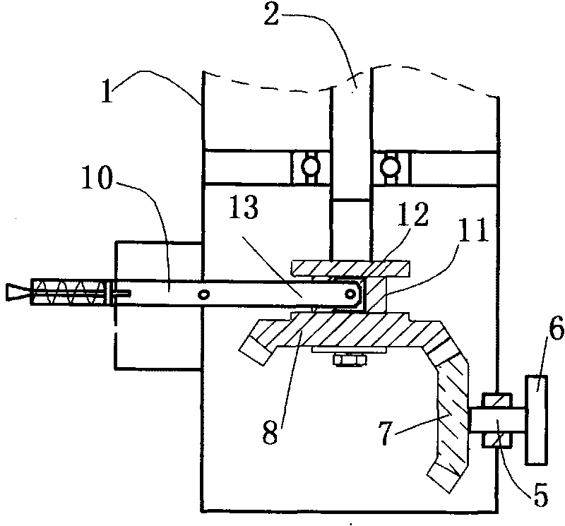
[0022] figure 2 Another depth indicator is shown, the bevel gear 2 8 can move axially along the screw rod 2, and the shift fork device 10 is installed on the frame 1, and the shift fork device 10 includes a driving rod 13 and a roller installed at the end of the driving rod 13 12. Bevel gear 2 8 is provided with dial groove 11, and roller 12 is inserted into dial groove 11. Shaking the driving lever 13 can make bevel gear 2 8 and bevel gear 1 7 separate or engage.

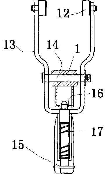
[0023] image 3 show figure 2 An embodiment of the shift fork device in the shown embodiment, the shift fork device includes a shift lever 13 and a roller 12 movably connected to the front end of the shift lever 13. It is flexibly connected and can make the driving lever 13 rotate around the pivot pin 14, the rear end of the driving lever 13 is equipped with a movable movable handle 15, and the front end of the movable handle 15 can be snapped into the positioning hole 16 on the frame 1, and the movable handle ...

Embodiment 3

[0025] Figure 4 Another depth indicator is shown. The shifting fork device 10 includes a dialing ring 21 that is movable in the dialing groove 11. The dialing ring 21 is fixedly connected to a locking device 23 through a connecting rod 22. The locking device 23 can be mounted on the frame 1. Move vertically, and can be fixed on the frame 1 at different positions. When the bevel gear 2 8 meshes with the bevel gear 1 7, the locking device 23 is released and moves vertically upwards, so that the bevel gear 2 8 and the bevel gear 1 7 Separate and lock the locking device 23 again to keep the bevel gear two 8 and the bevel gear one 7 in a separated state; The second bevel gear 8 is meshed with the first bevel gear 7, and the locking device 23 is locked again, so that the second bevel gear 8 and the first bevel gear 7 can be kept in the meshed state.


PUM


Abstract

The invention discloses a depth indicator which is used for indicating the running position of a mine lifting device, comprising a frame and a rotatable screw which is vertically installed on the frame; the indicator is installed on the screw; a scaling stripe is installed on the frame; one end of a horizontal axis which is flexibly connected on the frame is provided with a rotating wheel and the other end is provided with a first bevel gear; the lower end of the screw is provided with a second bevel gear; and the first bevel gear and the second bevel gear are meshed with each other. The invention has simple structure, easy manufacturing, convenient maintenance, low manufacturing cost and good application prospect.

Description

technical field [0001] The invention relates to a depth indicator, in particular to a depth indicator for indicating the operating position of a mine hoisting device. Background technique [0002] At present, most of the known depth indicators use a gearbox (reducer) with a worm gear to change the speed and direction, and convert the motion of the winch into the rotation of the screw, and the indicator on the screw moves up and down when the screw rotates. Correspond to the data on the scale bar to determine the depth position of the lifting device in the mine. This technical solution has a complex structure, especially the gearbox with worm gear is difficult to process, the cost is high, and assembly and maintenance are inconvenient. Contents of the invention [0003] The present invention aims to provide a depth indicator with simple structure, low cost and convenient maintenance. [0004] The technical solution adopted by the present invention is: a depth indicator, i...

Claims


Application Information

Patent Timeline
Patent Type & Authority Applications(China)
IPC IPC(8): B66B3/02B66B19/06
Inventor 邓鹰梁庆前梁轶
Owner 湖南金三星煤机制造有限公司
Why Eureka
Try Eureka