Heat sink wall panel structure arrangement for increasing absorption of plume gas

A technology of gas adsorption and structural layout, which is applied in the testing of machines/structural components, testing of engines, measuring devices, etc. It can solve problems such as differences in the capture rate of gas molecules on helium plates, and achieve high plume adsorption efficiency and high pumping speed , the effect of increasing the capture rate

Inactive Publication Date: 2010-06-02
BEIHANG UNIV
View PDF0 Cites 13 Cited by
  • Summary
  • Abstract
  • Description
  • Claims
  • Application Information

AI Technical Summary

Problems solved by technology

Actually, depending on the type of gas and its temperature, the area of ​

Method used


Image

  • Heat sink wall panel structure arrangement for increasing absorption of plume gas
  • Heat sink wall panel structure arrangement for increasing absorption of plume gas
  • Heat sink wall panel structure arrangement for increasing absorption of plume gas

Examples


Embodiment Construction

[0013] The present invention will be further described below in conjunction with the accompanying drawings.

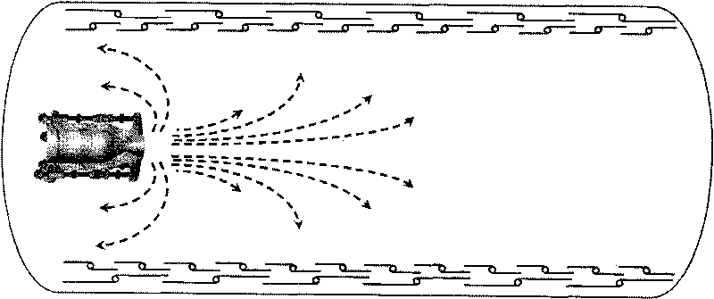
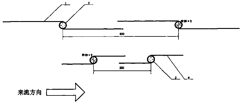
[0014] figure 1 The heat sink wall plate used for the plume test is mainly composed of liquid nitrogen heat sink fins (1), liquid nitrogen heat sink branch pipes (2), liquid helium heat sink branch pipes (3), liquid helium heat sink fins ( 4) Composition, the commonly used wall panels are welded by copper fins and stainless steel branch pipes, in which liquid nitrogen or liquid helium refrigeration medium is passed through the stainless steel branch pipes.

[0015] The distance between the stainless steel tubes of the liquid nitrogen heat sink is 400mm, and the size of the stainless steel tubes is Φ20×2; the distance between the stainless steel tubes of the liquid helium heat sink is 200mm, and the size of the stainless steel tubes is Φ20×2. The size form of the heat sink wall plate can ensure the uniformity of the heat sink temperature and meet the experimental requi...


PUM


Abstract

The invention relates to a heat sink wall panel for plume test, mainly consisting of a liquid nitrogen heat sink fin (1), a liquid nitrogen heat sink branch pipe (2), a liquid nitrogen heat sink branch pipe (3) and a liquid nitrogen heat sink fin (4). The liquid nitrogen heat sink is located inside the liquid nitrogen heat sink to reduce the heat load of a vacuum container to the liquid nitrogen heat sink; the liquid nitrogen heat sink directly faces to the gas in plume test ensuring high pumping speed and high plume absorption efficiency; the opening direction of the liquid nitrogen heat sink wall panel is opposite to the direction of the plume, and the plume gas can rapidly enter into the liquid nitrogen heat sink and the liquid nitrogen heat sink interlayer to reduce the plume ejection sped and improve the absorption efficiency via multiple bounce; the opening direction of the liquid nitrogen heat sink wall panel is in the plume direction and is in geometric symmetry with the opening direction of the liquid nitrogen heat sink wall panel so that the plume gas is easy to enter and difficult to come out, the capturing rate of gas is increased; gap is left between the fins so that both sides of the heat sink can absorb flume gas, thereby effectively increasing the plume absorption area; and the materials adopt stainless steel branch pipes and copper fins, thereby effectively improving the static and dynamic vacuum degree inside the vacuum container.

Description

【Technical field】 [0001] The present invention relates to a form of heat sink panel structure layout for increasing plume gas adsorption. The invention is particularly applicable to the structural layout form of the heat sink wall plate of the cylindrical section that increases the plume gas adsorption. 【Background technique】 [0002] The attitude and orbit control engines widely used on artificial satellites, spacecraft, space stations, deep space probes, missiles and launch vehicles, when working in a high-altitude thin environment, their jets will expand freely to the external environment to form a vacuum plume. The plume will have plume effects such as plume pollution, plume disturbance force and plume thermal effect on the spacecraft. These effects can reduce the performance of working components at least, and lead to the failure of flight missions at worst. With the rapid development of the aerospace industry, the aerospace design department is paying more and more a...

Claims


Application Information

Patent Timeline
IPC IPC(8): G01M15/00
Inventor 凌桂龙蔡国飙王文龙李晓娟黄本诚张国舟
Owner BEIHANG UNIV
Why Eureka
Try Eureka