Winding device and winding method

A winding device and winding head technology, applied in transportation and packaging, climate sustainability, non-aqueous electrolyte batteries, etc., can solve uneven tightness, deformation of battery cells, and difficulty in ensuring the regular shape of lithium-ion batteries, etc. problems, to achieve the effect of balancing the degree of tightness, preventing deformation, and maintaining stable winding tension

Active Publication Date: 2010-06-02
GEESUN AUTOMATION TECH
View PDF0 Cites 15 Cited by
  • Summary
  • Abstract
  • Description
  • Claims
  • Application Information

AI Technical Summary

Problems solved by technology

It is precisely because of this difference in linear speed that the pulling force of the pole piece driven by the winding needle 1 is also different in different states: that is, the winding tension of the pole piece is larger when the winding needle 1 is in the horizontal state, and the winding tension of the pole piece is larger when the winding needle 1 is in the vertical state. In this state, the winding tension of the pole piece is small, therefore, the degree of tightness of the pole piece wound on the winding needle 1 is uneven, and it is easy to deform the coiled products such as the electric core formed by winding the pole piece, and it is difficult to ensure that the lithium ion The battery has a regular shape

Method used


Image

  • Winding device and winding method
  • Winding device and winding method
  • Winding device and winding method

Examples


no. 2 Embodiment approach

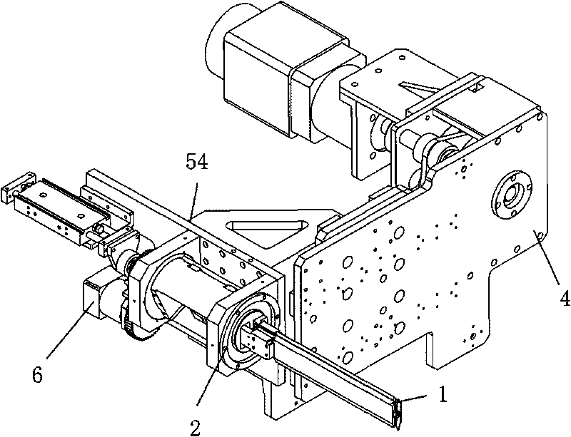
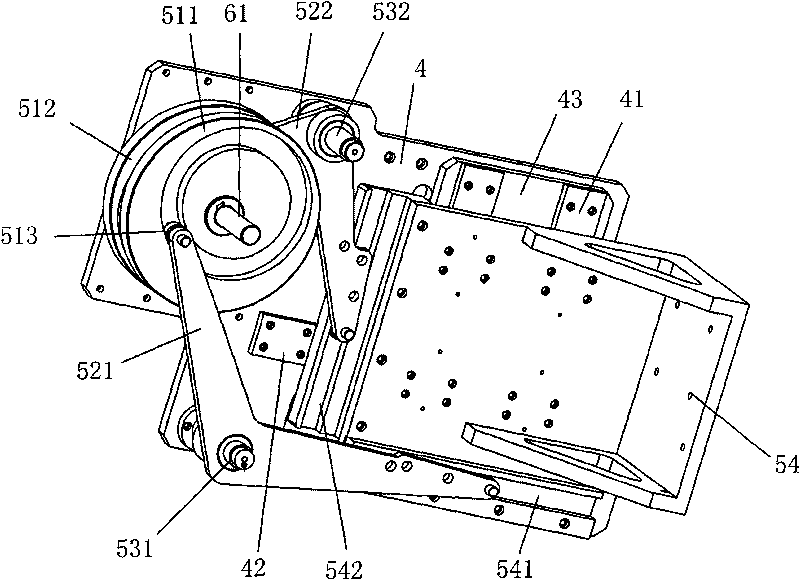
[0044] Such as image 3 and Figure 5 As shown, similarly, the base 4 can also form a lateral movement pair with the winding head mounting part 54. For example, the base 4 includes a second guide rail 42 arranged laterally, and the winding head mounting part 54 can also be left and right along the second guide rail 42. move. In order to smoothly realize the winding head mounting part 54 to slide longitudinally and laterally along the first guide rail 41 and the second guide rail 42 respectively, a cross displacement plate 43 can also be added on the base 4, for example, the first guide rail 41 can be arranged on on the cross displacement plate 43 , and the cross displacement plate 43 and the second guide rail 42 form a lateral movement pair.

[0045] The driving mechanism 51 in this embodiment further includes a second driving mechanism 512 , the swing rod further includes a second swing rod 522 , and the bearing seat 53 further includes a second bearing seat 532 . The midd...

no. 3 Embodiment approach

[0050] Such as Figure 8 In the embodiment shown, the compensation control member that controls the strip material 3 to carry out linear velocity compensation motion includes a strip control lever 55 for controlling the strip material 3 to perform transverse linear velocity compensation movement, and one end of the strip control lever 55 is connected to the swing rod. 52 is hinged, and the other end forms a lateral movement pair with the base plate 4. Specifically, the base plate 4 also includes a third guide rail 43 arranged laterally, and the strip material control lever 55 also includes a third slider, which can slide laterally along the third guide rail 43 and simultaneously control the left and right swing of the strip material 3 to realize lateral movement. Line speed compensation.

[0051] For example, when the driving mechanism 51 rotated along the direction of the arc arrow, the end of the fork 52 connected to the tape control rod 55 moved to the right, and the tape ...


PUM


Abstract

The invention discloses a winding device and a winding method. The winding device comprises a winding head 2, a winding needle 1 arranged on the winding head 2 and rotating with the winding head 2 for a strip material 3 to wind, and a winding driving mechanism for controlling the strip material 3 or the winding head 2 to perform the linear velocity compensating motion to stabilize a linear velocity of the strip material 3 in a certain range. The technical scheme provided by the invention can control the strip material or the winding head in the winding device to perform the linear velocity compensating motion to make the linear velocity of the winding needle for rotating to drive the strip material and a linear velocity generated when the winding needle or the strip material performs the linear velocity compensating motion relatively complemented, keeps a stable winding tension and effectively prevents the winding product from deforming.

Description

technical field [0001] The invention relates to a winding device and a winding method. Background technique [0002] Such as figure 1 , in an existing winding device, the flat winding needle 1 installed on the winding head 2 rotates at a constant speed around its rotating shaft 11, so that the strip material 3 from above or on one side of the winding needle 1 is wound on the winding needle 1 However, due to the different linear speeds at which the winding needle 1 pulls the strip material 3 under different motion states, the tension of the strip material 3 during the winding process is uneven, and the product formed by winding the strip material 3 is easily deformed. [0003] For example figure 1 When winding a cell for a square lithium-ion battery, the strip material 3 is a pole piece, and the pole piece coming from directly above the winding needle 1 is driven by the winding needle 1 and gradually moves along the movement track of the core entry point 12 of the winding n...

Claims


Application Information

Patent Timeline
Patent Type & Authority Applications(China)
IPC IPC(8): H01M10/058
CPCB65H51/20B65H2701/37B65H59/38H01M2010/0495B65H54/10Y02E60/10Y02P70/50
Inventor 阳如坤徐国根
Owner GEESUN AUTOMATION TECH
Why Eureka
Try Eureka