Differential feed half-wave length antenna with harmonic suppression function

A technology of differential feeding and harmonic suppression, applied to antennas, electrical components, etc., can solve the problems of not being able to provide sufficient suppression of harmonic bandwidth, reduce antenna gain and efficiency, etc., achieve easy processing, reduce interference, and suppress secondary The effect of harmonics

Inactive Publication Date: 2012-08-22
SOUTH CHINA UNIV OF TECH
View PDF0 Cites 1 Cited by
  • Summary
  • Abstract
  • Description
  • Claims
  • Application Information

AI Technical Summary

Problems solved by technology

The above methods are to change the harmonic frequency to make it deviate from the integer multiple of the fundamental frequency, but the energy of the harmonic signal will also be radiated by the antenna; Y.J.Sung in "An Improved Design of Microstrip Patch Antennas Using Photonic Bandgap Structure" (IEEE Transactions On Antennas And Propagation, Vol.53, No.5, pp1799-1804, May 2005) proposes a microstrip antenna based on PBG structure, which reflects the harmonic signal from the input port of the antenna, but the PBG structure will introduce additional Insertion loss, thereby reducing the gain and efficiency of the antenna, and as Hyungrak pointed out in the article "Microstrip-Fed Slot Antennas With Suppressed Harmonics" (IEEE Transactions On Antennas And Propagation, Vol.53, No.9, pp2809-2817, May2005) , the above design does not provide sufficient rejection in the harmonic bandwidth

Method used


Image

  • Differential feed half-wave length antenna with harmonic suppression function
  • Differential feed half-wave length antenna with harmonic suppression function
  • Differential feed half-wave length antenna with harmonic suppression function

Examples


Embodiment 1

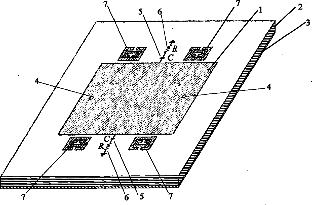
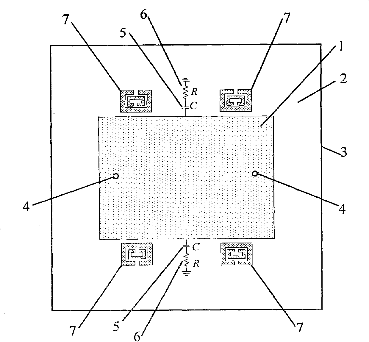
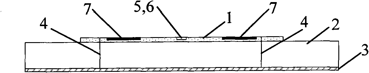
[0025] Such as Figure 1-3As shown, a differentially fed half-wavelength antenna includes an upper radiation patch 1, an intermediate dielectric substrate 2 and a bottom metal floor 3; One end of the electrical probe 4 is connected to the upper radiation patch 1 and the other end is connected to the coaxial feed port of the bottom metal floor 3 through the intermediate dielectric substrate 2 . When the port is matched with the antenna, the signal can be fed into the antenna, and the antenna resonates to radiate the energy. The antenna is fed by a pair of parallel probes 4 . Two matching attenuation networks are respectively connected to the lateral side of the upper radiation patch 1 on the symmetrical line of the two feeding points 4 of the upper radiation patch 1, and the symmetrical line of the two feeding points 4 is the lateral midline. The matching attenuation network includes a capacitor 5 and a resistor 6, the capacitor 5 and the resistor 6 are connected in series, t...

Embodiment 2

[0028] Such as Figure 4-6 As shown, a typical differentially fed half-wavelength antenna with harmonic radiation suppression function includes an upper radiation patch 1, a first dielectric substrate 4, a probe layer 2, a second dielectric substrate 5 and a bottom metal floor 3; A first dielectric substrate 4 is provided between the upper radiation patch 1 and the probe layer 2, and a second dielectric substrate 5 is provided between the probe layer 2 and the bottom metal floor 3; the two probes 4 are located vertically on the second dielectric substrate 5 On the center line of the side, one end of the feed probe 10 is connected to the probe layer 2 to feed the upper radiation patch 1 through coupling, and the other end is connected to the coaxial feed port of the bottom metal floor 3 through the dielectric substrate 5 . When the port is matched with the antenna, the signal can be fed into the antenna, and the antenna resonates to radiate the energy. Two matching attenuatio...


PUM


Abstract

The invention discloses a differential feed half-wave length antenna with a harmonic suppression function. Two matched attenuation networks are arranged on the symmetric lines of two feed points on the differential feed half-wave length antenna; the two matched attenuation networks are connected with horizontal edges of an upper radiation patch respectively; and four rectangular complementary split ring resonators are arranged at the place 0.2 to 0.8mm far away from the outsides of two horizontal edges of the upper radiation patch and L / 3 far away from the symmetric lines of the two feed points of the antenna, wherein L is a half-wave length; c is a light velocity of a free space; epsilon eff is an effective dielectric constant of the differential feed half-wave length antenna; and f is aworking frequency of the differential feed half-wave length antenna. The matched attenuation networks are used for absorbing the energy of a second harmonic, and the rectangular complementary split ring resonators are used for suppressing a third harmonic. The harmonics of the antenna of the invention can be suppressed and the effect on a fundamental frequency characteristic is extremely low. Thedifferential feed half-wave length antenna also has the characteristics of small volume, easy processing, low cost and the like.

Description

technical field [0001] The invention relates to a microwave antenna, in particular to a differential feeding half-wavelength antenna with harmonic suppression function, which can be applied to the fields of mobile communication, satellite communication, microwave communication, wireless sensor network and the like. Background technique [0002] In recent years, wireless communication systems have increasingly stringent requirements on antennas. Because of the advantages of small size, light weight, superior performance, low price and easy manufacturing, microstrip antennas have become the focus of satellite communications and wireless mobile communications. They are used to receive wireless signals in the air or transmit RF active circuits connected to them. signal of. In active radio frequency circuits, differential circuits are widely used in radio frequency integrated circuits (RFICs) and monolithic microwave integrated circuits (MMICs) due to their many advantages such ...

Claims


Application Information

Patent Timeline
Patent Type & Authority Patents(China)
IPC IPC(8): H01Q13/08
Inventor 胡斌杰章秀银潘爵雨
Owner SOUTH CHINA UNIV OF TECH
Why Eureka
Try Eureka