Compound power-generating shoe

A technology for power generation shoes and power generation devices, applied in footwear, electrical components, electromechanical devices, etc., can solve the problems of small power generation, underutilization or full utilization, and power generation limited by conditions, and achieves the effect of reducing resource consumption and high efficiency

Inactive Publication Date: 2012-08-29
刘新广
View PDF6 Cites 1 Cited by
  • Summary
  • Abstract
  • Description
  • Claims
  • Application Information

AI Technical Summary

Problems solved by technology

However, the power generation of the former is too small, and the power generation of the latter is limited by conditions, neither of which utilizes or fully utilizes the energy of human walking

Method used


Image

  • Compound power-generating shoe
  • Compound power-generating shoe
  • Compound power-generating shoe

Examples


Embodiment 1

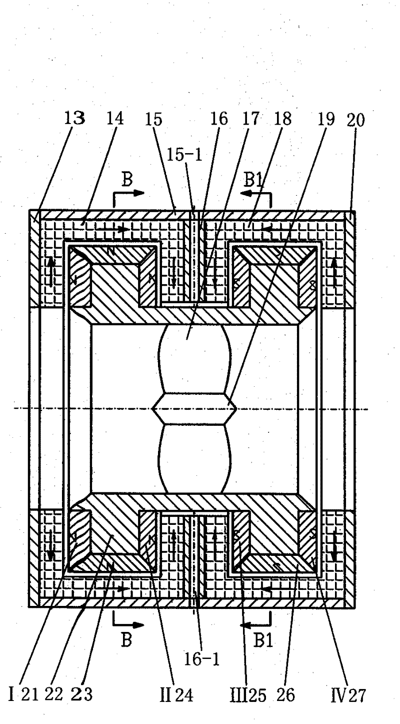
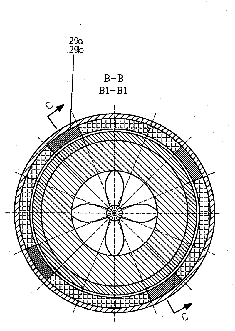
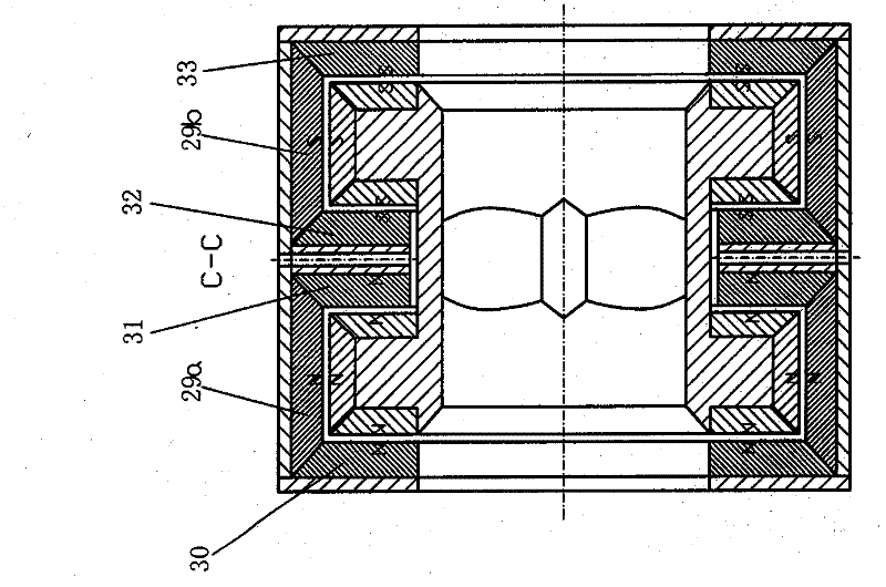
[0027] The generator F consists of a stator and a rotor, such as Figure 3 to Figure 5 shown.

[0028] Rotor composition - the permanent magnet disks I21, II24, III25, IV27 magnetized in the axial direction and the permanent magnet rings 23, 26 magnetized in the radial direction are consolidated on the convex edge of the magnetic conduction ring 22, and the permanent magnets The outer surface of disc I21, permanent magnet ring 23, permanent magnet disc II24 is N pole, makes the outer surface of permanent magnet disc III25, permanent magnet ring 26, permanent magnet disc IV27 be S pole; The top is fixed on the inner circle of the magnetic conduction ring 22, and the other end of the blade 17 is fixed on the outer circle of a cylinder 19 with tapers at both ends to form an impeller. The center line of the cylinder 19 coincides with the axis of the magnetic conduction ring 22, and the guide The left and right ends of the inner circle of the magnetic ring 22 are conical openings ...

Embodiment 2

[0036] When the back and the front of the soles alternately press down on the front and back soft capsules, the fluid is forced to impact the impeller 35-3 to drive the generator 35-1 to generate electricity.

[0037] Embodiment three: as Figure 8 Figure 9 Show. The tube 36 connects the two soft bags along the length of the shoe; the tube 36 is surrounded by corresponding magnetic plates 36-1 and 36-2 up and down, and conductive plates 36-2 and 36-4 corresponding to the left and right to form the power generating device , the section of the tube 36 is a rectangular circle; the conductive plates 36-2 and 36-4 are connected to the input end of the charging controller; the tube 36 is filled with conductive fluid in the two soft bags.

Embodiment 3

[0038] When the back and the front of the sole of the foot alternately press down on the front and back soft capsules, the conductive fluid is forced to flow in the tube 36 and cut the magnetic lines of force between the magnetic plates 36-1 and 36-2 to generate flow directions corresponding to the left and right in the conductive fluid. The conductive plates 36-2 and 36-4 induce electricity, and the conductive plates 36-2 and 36-4 transmit the induced electricity to the charging controller.

[0039] Embodiment four: as Figure 10 to Figure 12 Show. The non-magnetic insulating pipe 40 connects the two soft bags along the length of the shoe; in the non-magnetic insulating pipe 40, a rolling magnetic ball or a magnetic roller 38 is placed, and the two ends of the pipe 40 are provided with arc-shaped stoppers 37 and arc-shaped stoppers. Block 41, the arc stopper 37 is the same as the arc stopper 41, and the coil 39 is wound on the outer circle of the non-magnetic insulating pipe...


PUM


Abstract

The invention relates to a compound power-generating shoe, comprising an upper sole and a lower sole. Curved non-magnetic insulation tubes wound with coils outside, a charge controller and storage batteries are arranged along the shoe-length direction; rollable magnetic balls or magnetic cylindrical rollers are placed inside the insulation tubes; one collapsible soft capsule is respectively arranged at the front part and back part of the upper sole, the two soft capsules are connected by a pipe, the two soft capsules and the pipe are filled with fluid inside, a power generation assembly is arranged on the pipe; the coils, output terminals of the power generation assembly are both connected with the charge controller, while the charge controller is connected with the storage batteries. When people walk wearing the compound power-generating shoe, the magnetic balls or magnetic cylindrical rollers roll, the magnetic lines of force penetrate through the tube wall of the curved non-magnetic insulation tubes and sweep over each circle of the coils in proper sequence; as a result, the coils induce electricity; the back part and front part of sole of the foot alternatively press the frontand the back soft capsule, when one of the soft capsule is compressed, the fluid inside is forced to flow to drive the power generation assembly on the pipe to generate power. The compound power-generating shoe of the invention generates power easily and protects health of the people.

Description

technical field [0001] The invention relates to power generation technology, in particular to a composite power generation shoe. Background technique [0002] People have tried to use the human body to generate electricity. For example, it has been disclosed that the use of the beating energy of the human heart or pulse to generate electricity has achieved some results, in an attempt to power mobile phones; there are also people who propose to use a power generation device developed by pedestrians to trample in public places with dense crowds to generate electricity. But the former generates too little power, the latter is limited by conditions, and both do not utilize or make full use of the energy of people walking. Contents of the invention [0003] The purpose of the invention is to make full use of the energy generated by people's walking to generate electricity, and collect the generated electric energy, or to charge portable electronic products. [0004] The prese...

Claims


Application Information

Patent Timeline
Patent Type & Authority Patents(China)
IPC IPC(8): A43B7/04H02K35/02A43B3/35
Inventor 刘新广
Owner 刘新广
Why Eureka
Try Eureka