

Vacuum heat pump type distilling apparatus
A distillation device and vacuum technology, applied in the field of distillation machines, can solve the problems of large electric power consumption, environmental pollution, large energy consumption, etc., and achieve the effects of improving utilization rate, improving economic benefits, and reducing emissions
Inactive Publication Date: 2010-06-09
凌建军
View PDF0 Cites 20 Cited by
- Summary
- Abstract
- Description
- Claims
- Application Information
AI Technical Summary
Problems solved by technology
[0004] In addition to drinking, distilled water is also widely used in electroplating industry, pharmaceutical industry, food processing industry, wine making industry, beverage industry and other industries, because distilled water not only consumes a lot of electric energy under the current process conditions, but also consumes a lot of cooling water , so the price is more expensive,
Method used
View moreImage
Smart ImageViewing Examples

Examples
Example Embodiment
[0040] Other embodiments
Login to View More PUM
 Abstract
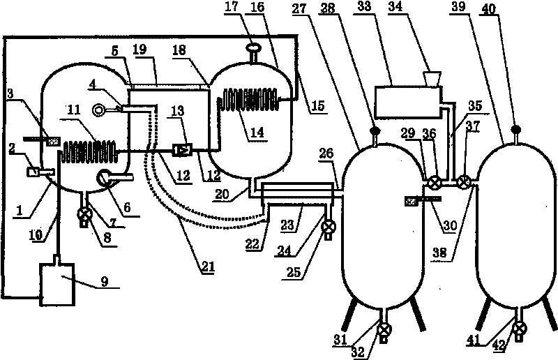
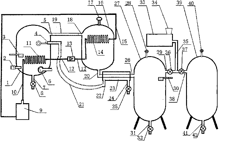
The invention discloses a vacuum heat pump type distilling apparatus which comprises a program controller, an evaporating tank assembly, a condensing tank assembly, a distilled water tank assembly, a vacuum buffer tank assembly, a vacuum pump, an air inlet pipe of the vacuum pump, an air exhaust hole of the vacuum pump, an electrical bar, a compressor, a high-temperature condenser, a low-temperature evaporator, a compressor outlet pipeline, a compressor inlet pipeline, a connecting pipe and a throttling valve. In the invention, first, the vacuum pump is used for pumping the device into a vacuum state so that the boiling temperature of the water is lowered and the heat pump can meet the temperature requirement; then, the low-temperature evaporating pipe of the heat pump is used for absorbing the energy of high-temperature steam to heat the water; and meanwhile, after the heat of the high-temperature steam is absorbed, the high-temperature steam is condensed into distilled water, the cooling process of the high-temperature steam can not consume any tap water, the power can be saved by more than 80%, and the water can be saved by more than 90%. In order to solve the problem that the heat source is insufficient when the heat pump is just started, the electrical bar is used for heating the water to the specified temperature in the starting process.
Description
Technical field [0001] The present invention relates to a distillation machine, in particular to a vacuum heat pump type distillation device, which can be a water distiller, a seawater distillation machine, a salt solution distillation machine, an acid solution distillation machine, an alkali solution distillation machine, a wine distillation machine, a crude oil distillation machine , Heavy metal wastewater distillation machine, electroplating wastewater distillation machine, cyanide sewage distillation machine, liquid chemical raw material distillation machine, liquid medicine distillation machine, liquid food distillation machine, sewage distillation machine, toxic waste water distillation machine. Background technique [0002] With the expansion of population and the rapid development of industry, water consumption is increasing day by day, and water pollution is also becoming more and more serious. The annual discharge of sewage in the world is now more than 690 billion...
Claims
Login to View More Application Information
Patent Timeline
 IPC IPC(8): B01D3/10C02F1/04
Inventor凌建军黄鹂
Owner凌建军