Centrifugal sand grain separation device and implementation method

A separation device and centrifugal technology, applied in chemical instruments and methods, solid separation, grading, etc., can solve the problems of not having the value of generalization and application, unsuitable angle and density of the screen surface, and high labor intensity, etc., to achieve The effect of simple structure, high degree of automation and large processing capacity

Inactive Publication Date: 2010-06-09
TIANJIN DAGANG OILFIELD GROUP ENG CONSTR +1
0 Cites 24 Cited by

AI-Extracted Technical Summary

Problems solved by technology

Even if a small number of projects with high requirements are used to sort sand, water washing or winnowing is generally used. Due to the limitations of sewage treatment and environmental pollution, these methods do not have the value of general application
At the ...

Abstract

The invention relates to a centrifugal sand grain separation device and an implementation method. The centrifugal sand grain separating device comprises a speed regulating motor, a feeding device, a discharging device, a primary separation device, a secondary separation device, a collecting device and a conveying device. The primary separation device consists of a bulk material disc and a bulk material range controller, wherein the bulk material disc is a steel conical barrel or a steel disc connected with a main shaft of the motor, and the bulk material range controller consists of a steel cylinder and a steel truncated cone cylinder. The secondary separation device is a bulk material disc connected with the main shaft of the motor, the size of the bulk material disc is greater than thatof a primary bulk material disc, and the secondary separation device is a steel disc or a steel fan blade capable of adjusting angles. The centrifugal sand grain separation device can effectively separate sand grains with the grain size more than or less than certain grain size (a controlled diameter) so that separated sand materials meet the requirements on engineering application. The centrifugal sand grain separation device has the advantages of the separation of thick and thin sand grains, high automation degree, time and labor saving, simple structure, durability, easy repair, large treatment quantity and high separation efficiency.

Application Domain

Technology Topic

Image

  • Centrifugal sand grain separation device and implementation method
  • Centrifugal sand grain separation device and implementation method
  • Centrifugal sand grain separation device and implementation method

Examples

  • Experimental program(1)

Example Embodiment

[0030] The technical solution of the present invention will be further described in detail below with reference to the drawings and embodiments:
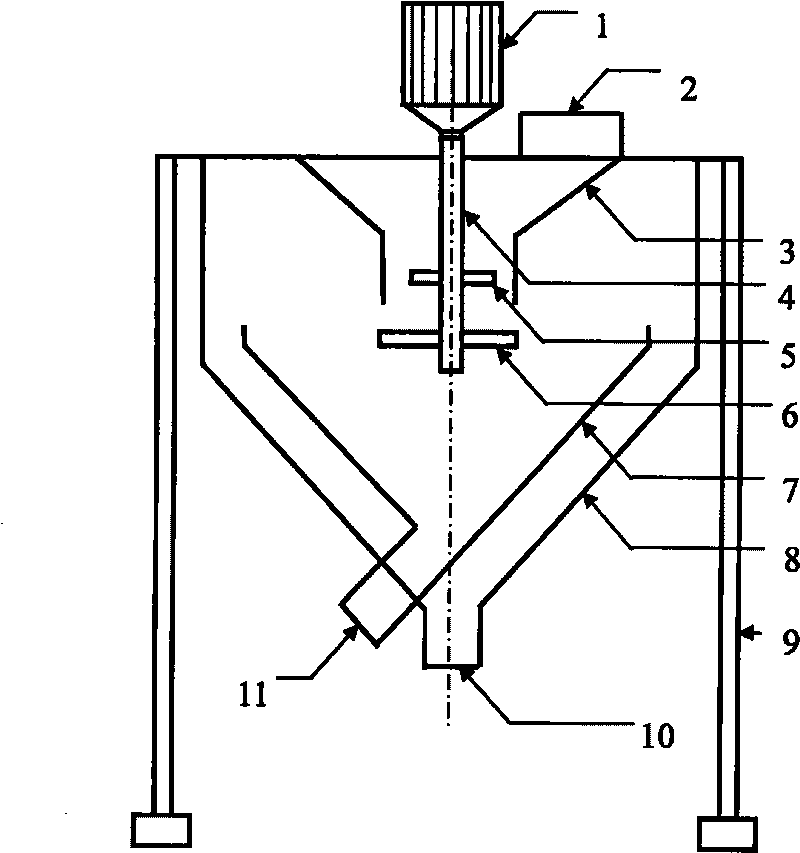
[0031] Such as figure 1 As shown, 1 speed-regulating motor, 2 feeding port, 3 bulk material range controller, 4 main shaft, 5 first-level bulk tray, 6 second-level bulk tray, 7 inner cylinder, 8 outer cylinder, 9 support frame, 10 Coarse sand discharge port, 11 fine sand discharge port.
[0032] The motor 1 is located at the top of the centrifugal sand separator, the support frame 9 is connected to the outer cylinder 8; the top of the outer cylinder 8 is a whole piece of steel plate, and a rectangular hole is opened at the position of the inlet 2; the bulk material range controller 3 The upper part is connected with the steel plate on the top of the outer cylinder 8, the lower part is connected with the side wall of the outer cylinder 8; the upper part of the main shaft is connected with the speed-regulating motor shaft, and the lower part is connected with the side wall of the outer cylinder 8; the first-level bulk tray 5 is fixedly installed on the main shaft; The first-level bulk tray 6 is located at the lower part of the first-level bulk tray 5, and is also installed on the spindle, and its position can be adjusted up and down along the spindle direction; the top of the inner cylinder 7 is connected with the side wall of the outer cylinder 8 through the support frame 9; the top of the outer cylinder 8 and The middle part of the cone-shaped cylinder is connected with the four supporting and fixing posts of the supporting frame.
[0033] The principle of centrifugal separation of sand particles: Sand is composed of sand particles of different sizes. Under the action of centrifugal force, sand particles are thrown out along the direction of centrifugal force. Large particles have a large mass and a long distance to be thrown. Small particles have a small mass. The throwing distance is short, so that the separation of large and small particles is realized.
[0034] The implementation method of sand separation includes the steps:
[0035] The throwing distance of sand particles depends on the size of the centrifugal force acting on the sand particles. The size of the centrifugal force depends on the linear velocity when the sand particles are thrown. The size of the linear velocity is closely related to the radius of the bulk disk and the spindle speed. The spindle speed can determine the controlled particle size of sand separation.
[0036] The centrifugal sand separation device of the present invention is mainly used to separate sand particles larger and smaller than a certain controlled particle size, so as to meet engineering application requirements. The processing capacity of the sand to be selected depends on the power and speed of the motor used. The greater the motor power and the higher the speed, the greater the output. When the motor power is more than 15 kilowatts, the hourly throughput is more than 50 tons, and the separation efficiency is more than 90%.

PUM

no PUM

Description & Claims & Application Information

We can also present the details of the Description, Claims and Application information to help users get a comprehensive understanding of the technical details of the patent, such as background art, summary of invention, brief description of drawings, description of embodiments, and other original content. On the other hand, users can also determine the specific scope of protection of the technology through the list of claims; as well as understand the changes in the life cycle of the technology with the presentation of the patent timeline. Login to view more.

Similar technology patents

Classification and recommendation of technical efficacy words

  • Simple structure
  • High degree of automation

Microlithographic projection exposure apparatus

InactiveUS20050068499A1Simple structureReliable and low-maintenance operationProjectorsPhotomechanical exposure apparatusCamera lensPhysics
Owner:CARL ZEISS SMT GMBH

Full-automatic flexible assembly line of light emitting diode (LED) bulb lamp

InactiveCN102896494AIncreased reliability and automationHigh degree of automationAssembly machinesLight sourceStructure based
Owner:SHANGHAI RADIO EQUIP RES INST
Why Eureka
Try Eureka