Flexible self-centering device with high stiffness

A high-rigidity, self-centering technology, applied to gear teeth manufacturing devices, gear teeth, gear cutting machines, etc., can solve the problems of complex structure, high cost, low precision, etc., and achieve large shrinkage and expansion range, low cost, and extended The effect of longevity

Inactive Publication Date: 2010-06-09
HANGZHOU JIE DRIVE TECH
View PDF0 Cites 1 Cited by
  • Summary
  • Abstract
  • Description
  • Claims
  • Application Information

AI Technical Summary

Problems solved by technology

[0008] In order to overcome the defects of low precision, short life, complex structure and high cost in existing self-centering devices, the present inve

Method used


Image

  • Flexible self-centering device with high stiffness
  • Flexible self-centering device with high stiffness
  • Flexible self-centering device with high stiffness

Examples


Embodiment Construction

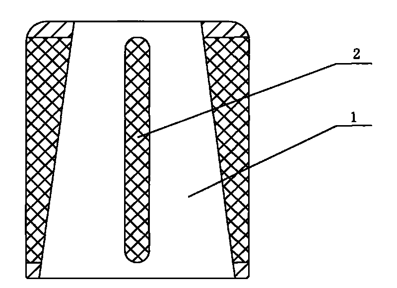
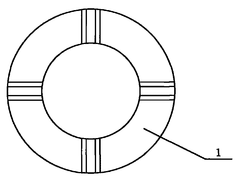
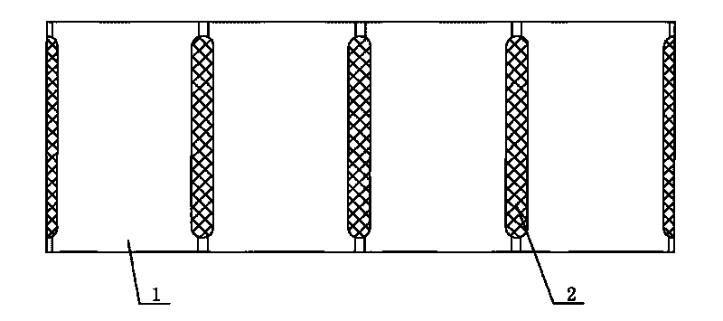
[0021] refer to Figure 1-3 , a flexible and high-rigidity self-centering device, including a plurality of positioning elements 1, and the positioning elements 1 are connected by rubber strips 2 to form an overall structure that is cylindrical on the outside and conical on the inside.

[0022] The positioning element 1 is a steel piece which has been quenched.

[0023] For the application of the present invention in gear grinding and gear hobbing fixtures, refer to Figure 4 , 5 .

[0024] The content described in the embodiments of this specification is only an enumeration of the implementation forms of the inventive concept. The protection scope of the present invention should not be regarded as limited to the specific forms stated in the embodiments. The protection scope of the present invention also extends to the field Equivalent technical means that the skilled person can think of based on the concept of the present invention.


PUM


Abstract

The invention relates to a flexible self-centering device with high stiffness, which comprises a plurality of positioning elements. The positioning elements are connected into an integral structure through rubber strips, the outer part of the integral structure is in a column shape, and the inner part forms a circular conical surface. The invention has the advantages of high precision, long service life, self-centering, simple structure and low cost.

Description

technical field [0001] The invention relates to a self-centering device for centering gear processing, in particular to a flexible and high-rigidity self-centering device. Background technique [0002] Gears are the basic parts of mechanical transmission. The gear grinding, hobbing, and shaving processes are the key processes of gear manufacturing. The centering accuracy of the grinding, hobbing, and shaving fixtures and the long life of the centering accuracy directly affect the gear. precision. [0003] There are four types of self-centering devices commonly used at present: elastic expansion sleeves, bellows sleeves, dense bead sleeves, and liquid plastic mandrels. [0004] The design of the elastic expansion sleeve is to separate continuous grooves in the circumferential direction of the expansion sleeve. The positioning mandrel is used to cooperate with the elastic expansion sleeve, and an axial force is applied to the end surface of the elastic expansion sleeve to mak...

Claims


Application Information

Patent Timeline
IPC IPC(8): B23F23/02
Inventor 陈德木谢信孚张永红
Owner HANGZHOU JIE DRIVE TECH
Why Eureka
Try Eureka