Robot automatic welding production line of middle groove and technological method thereof

A robot welding and automatic welding technology, which is applied in welding equipment, welding equipment, auxiliary welding equipment, etc., can solve the problems of poor welding quality, low work efficiency, and low production efficiency, and achieve complete and reasonable station settings and improve welding efficiency. Improvement of quality and welding efficiency

Active Publication Date: 2011-05-18
CHINA COAL ZHANGJIAKOU COAL MINING MACHINERY
View PDF0 Cites 0 Cited by
  • Summary
  • Abstract
  • Description
  • Claims
  • Application Information

AI Technical Summary

Problems solved by technology

The artificial gas shielded welding method is a traditional method commonly used at present. This method is not only difficult to guarantee the welding quality, but also has low work efficiency and high labor intensity; the method of using an automatic welding machine can only be used for the straight line welds of the middle plate and the bottom plate of the middle groove. Welding can not realize the curved welding of bent plates and rail seats, and the welding quality is not high; the known single-robot workstation method only uses one robot to hold a common welding gun to weld the straight line welds of the middle plate and the bottom plate, and does not weld bent plates, For the curved welding seam of the rail seat, the workstation exists in the form of an isolated point, and other related processes are separated from each other, no production line is formed, and the production efficiency is relatively low
In addition, there is currently no known robotic twin-wire welding process for casting central grooves

Method used


Image

  • Robot automatic welding production line of middle groove and technological method thereof
  • Robot automatic welding production line of middle groove and technological method thereof
  • Robot automatic welding production line of middle groove and technological method thereof

Examples


Embodiment 1

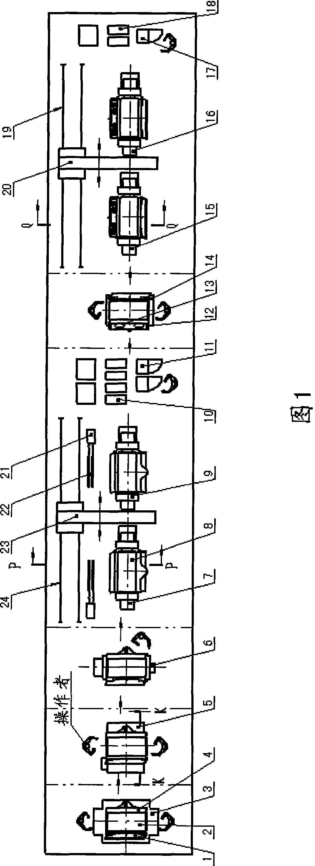
[0037] As can be seen from Fig. 1, the present invention designs 8 stations according to the manufacturing process direction of the middle tank and arranges them in a straight line, including the primary assembly station, the middle plate preheating station, the bottom welding station, the middle plate bottom plate robot welding workstation, the second There are 6 parts of the sub-assembly station and the bending plate rail seat robot welding workstation. The arrows indicate the logistics transfer direction of the workpiece, and the transfer of workpieces between each station is carried out by crane hoisting. The two workstations are controlled independently, using twin-wire digital double-pulse welding power supply. The robot, C-shaped frame, positioner, twin-wire elbow welding torch, and digital double-pulse welding power supply of each workstation are connected to the computer control system through their own cables. , controlled by a computer, can realize the automatic weld...

Embodiment 2

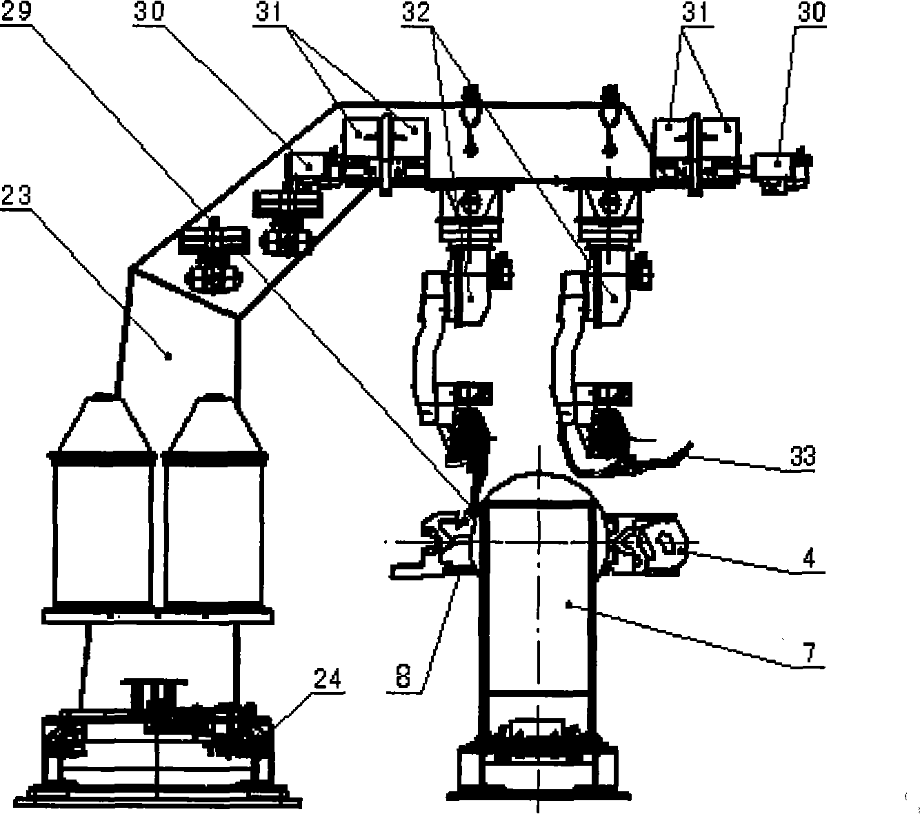
[0049] The difference between this embodiment and Embodiment 1 is that the bending plate rail seat robot welding workstation adopts another structural form, such as Figure 5 As shown, a set of horizontal guide rails 44 is installed on the side of the cross beam of the C-shaped frame 39, the robot 45 is side mounted on the horizontal guide rails, and can move laterally along the horizontal guide rails, and a single wire welding torch fixing frame is installed on one end of the frame cross beam 42. A single-wire elbow welding torch 40 with a contact welding seam starting position sensor installed on the head is clamped on this fixing frame, a double-wire welding torch fixing frame 46 is installed at the other end, and a contact welding torch is installed on the head. The double-wire elbow welding torch 47 of the type welding seam starting point positioning sensor is clamped on the fixture. Wire feeder 43 and welding torch cleaning device 41 are installed on the side of C-shaped...

Embodiment 3

[0052] The middle groove manufacturing process of the middle groove robot automatic welding production line is:

[0053] ①Primary assembly: Use the general assembly jig for the middle slot to manually assemble and point-align the blade groove side, middle plate, and baffle groove side at the primary assembly station, so that they have relatively correct positions to form components.

[0054] ② Middle plate preheating: transport the above components to the fixed high-efficiency flame preheating device for the middle plate at the second station, and perform flame preheating on the middle plate. The preheating temperature of the middle plate is controlled at 150-175°C to achieve After the temperature is reached, the flame will be automatically turned off by the flame control system.

[0055] ③ Bottom welding of the middle plate: When the workpiece error is large, so that the single-sided butt gap between the middle plate and the groove side is >2mm, the preheated components are i...


PUM

PropertyMeasurementUnit
diameteraaaaaaaaaa

Abstract

The invention relates to the technical field of production manufacturing of a cast middle groove by a heavy-duty scraper conveyor used on coal mines, and provides a robot automatic welding production line of a middle groove and a technological method thereof. The production line designs 8 stations according to the manufacturing process flow of the middle groove, comprises 6 parts of a primary assembly station, a middle plate preheating station, a backing welding station, a middle plate and bottom plate robot welding work station, a secondary assembly station and a bending rail rest robot welding work station, and forms an integrated production line layout of the middle groove. The invention integrates and uses multiple technologies of a welding robot, double-wire welding, digital double-pulse welding power source, computer control, high-efficiency flame preheating and the like, and establishes technical measures of preheating temperature, bevel form, welding sequence, welding parameters and the like; and the welding process is controlled by a computer, thereby realizing high-efficiency automatic robot welding of the middle groove in the overall process. Compared with the traditional manual gas shielded welding, the invention obviously improves the welding quality of the middle groove and increases the welding efficiency by 3-4 times.

Description

technical field [0001] The invention relates to the technical field of manufacturing a middle trough cast by a heavy-duty scraper conveyor used in coal mines, in particular to a central trough robot automatic welding production line and a process method thereof. Background technique [0002] The casting middle trough is the key part of the heavy-duty scraper conveyor in coal mine. It is assembled and welded by parts such as shovel plate trough side, baffle plate trough side, high-strength wear-resistant middle plate, bottom plate, curved plate, rail seat, etc. The structure is relatively complicated. Moreover, the requirements for welding technology are high and the welding is difficult. At present, there are three kinds of known technological methods in China: artificial gas shielded welding, automatic welding plane, and single robot workstation. The artificial gas shielded welding method is a traditional method commonly used at present. This method is not only difficult t...

Claims


Application Information

Patent Timeline
Patent Type & Authority Patents(China)
IPC IPC(8): B23K31/02B23K9/235B23K9/16B23K37/053B23K9/12B23K9/095
Inventor 李国平郑民会白虎曹文智单玉新韩效寿康绍光杨继武苗俊田
Owner CHINA COAL ZHANGJIAKOU COAL MINING MACHINERY
Why Eureka
Try Eureka