Draw bail of vane wheel and high-speed rotation shaft of high-speed centrifugal compression device

A technology of compression equipment and high-speed centrifugation, applied in mechanical equipment, rigid shaft couplings, components of pumping devices for elastic fluids, etc., can solve the problem of reducing the aerodynamic performance of the impeller, breaking the dynamic balance state of the high-speed rotor, and affecting the rotor Problems such as running stability, to achieve the effect of ensuring aerodynamic performance and convenient disassembly and assembly

Inactive Publication Date: 2010-06-09
WUXI COMPRESSOR CO LTD
View PDF0 Cites 25 Cited by
  • Summary
  • Abstract
  • Description
  • Claims
  • Application Information

AI Technical Summary

Problems solved by technology

The high-temperature shrink-fit assembly of this large interference design causes a large deformation of the high-speed shaft, especially the impeller after assembly. The deformation of the impeller will reduce the aerodynamic performance of the impeller, and the deformation of the high-speed shaft will even affect the impeller. In addition, when the impeller is disassembled and reinstalled, the dynamic balance state of the entire high-speed rotor is often destroyed due to lack of circumferential positioning.

Method used


Image

  • Draw bail of vane wheel and high-speed rotation shaft of high-speed centrifugal compression device
  • Draw bail of vane wheel and high-speed rotation shaft of high-speed centrifugal compression device

Examples


Embodiment Construction

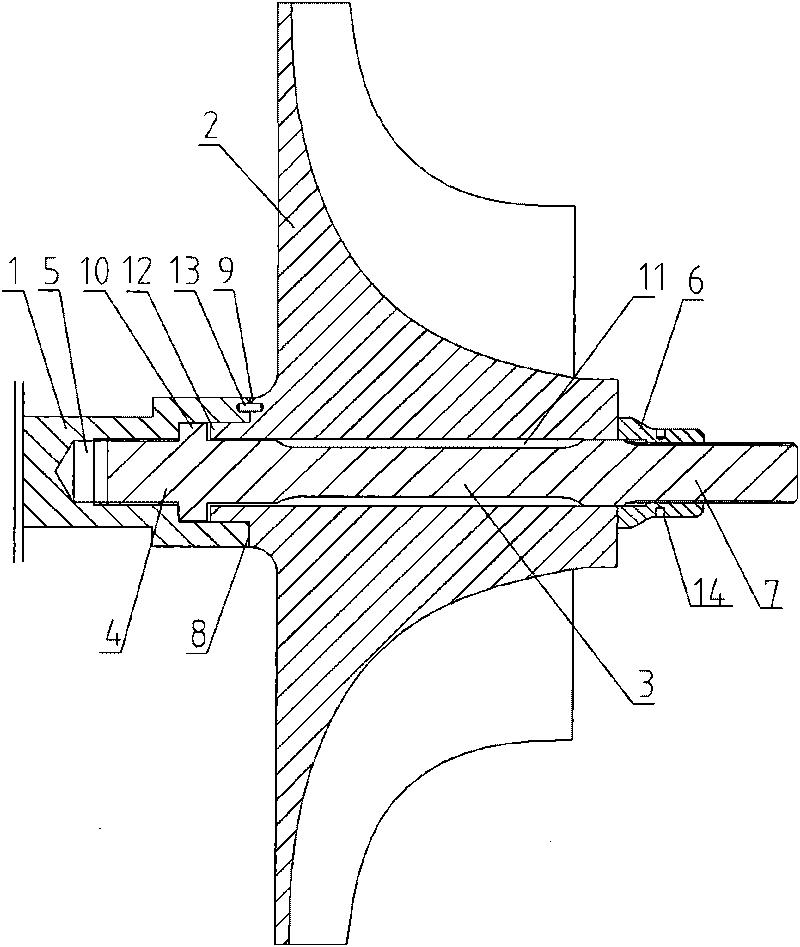
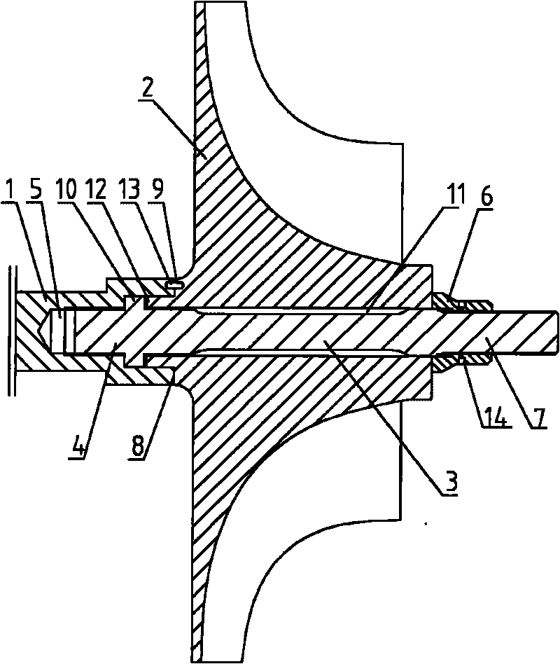
[0008] See figure 1 , the present invention includes a high-speed rotating shaft 1, an impeller 2, a stretching shaft 3 that runs through the center hole 11 of the impeller 2, one end 4 of the stretching shaft is threadedly connected to an internal threaded hole 5 at the end of the high-speed rotating shaft 1, and a compression nut 6 is set in the stretching shaft. The other end 7 of the shaft, the end face 8 of the high-speed rotating shaft is fastened to the outstretched journal 9 of the impeller 2, the end face of one end of the compression nut 6 is tightly connected to the end face of the impeller 2; Installed in the outer raised part 12 of the center hole 11, the end surface 8 of the high-speed rotating shaft has an inner hole, and the outwardly extending journal 9 of the impeller 2 is fastened to the inner hole of the end surface 8 of the high-speed rotating shaft through the positioning pin 13; Have turning hole 14.


PUM


Abstract

The invention relates to a draw bail of a vane wheel and a high-speed rotation shaft of a high-speed centrifugal compression device. The invention ensures that the high-speed rotation shaft and the vane wheel are not deformed and the assembly and disassembly are convenient. The draw bail comprises the high-speed rotation shaft and the vane wheel and is characterized in that a stretching shaft penetrates through a centre hole of the vane wheel, one end of the stretching shaft is connected with the inner screwed hole on the terminal of the high-speed rotation shaft by screw thread, a gland nut is sheathed on the other end of the stretching shaft, the end surface is fixedly connected with an outrigger shaft neck of the vane wheel, and the end surface of one end of the gland nut is fixedly connected with the end surface of the vane wheel.

Description

(1) Technical field [0001] The invention relates to the technical field of compression equipment, in particular to a connection structure between an impeller and a high-speed rotating shaft on a high-speed centrifugal compression equipment. (2) Background technology [0002] Existing high-speed centrifugal compression equipment includes a centrifugal compressor and a centrifugal blower, and the shrink-fit method is used to directly assemble the impeller on the end of the high-speed rotating shaft. This structure usually needs to choose a larger interference to ensure that the impeller does not loosen during high-speed rotation. For this reason, the impeller or high-speed rotating shaft must be heated to a higher temperature before assembly. The high-temperature shrink-fit assembly of this large interference design causes a large deformation of the high-speed shaft, especially the impeller after assembly. The deformation of the impeller will reduce the aerodynamic performance...

Claims


Application Information

Patent Timeline
Patent Type & Authority Applications(China)
IPC IPC(8): F04D29/28F04D29/054
CPCF16D1/076
Inventor 任启锋蒋尚鸿杨彭华
Owner WUXI COMPRESSOR CO LTD
Why Eureka
Try Eureka