Automobile engine cooling fan

A technology for automobile engines and cooling fans, which is applied in the direction of machines/engines, liquid fuel engines, mechanical equipment, etc. It can solve the problems of reducing the service life of the fan, unbalanced force on the blades, and affecting the performance of the fan, so as to improve the air volume and air pressure. Improve the rigidity and strength, increase the effect of the effective work area

Inactive Publication Date: 2009-08-12
WENZHOU YILONG AUTO PARTS CO LTD
View PDF7 Cites 1 Cited by
  • Summary
  • Abstract
  • Description
  • Claims
  • Application Information

AI Technical Summary

Problems solved by technology

[0004] Generally, fans are injection molded, and their inherent internal stress forces the blades to squeeze the hub, especially for annular fans, which will cause unnecessary deformation of the fan during aging and affect the overall performance of the fan
The ribs of the hub of the ordinary annular fan are made of strip-shaped ribs. This structure is simple to open the mold, but the stability is poor and the deformation is large, which leads to uneven force on each blade, reduces the balance performance, and causes the fan to vibrate during operation. , increases the noise and reduces the service life of the fan

Method used


Image

  • Automobile engine cooling fan
  • Automobile engine cooling fan

Examples


Embodiment 1

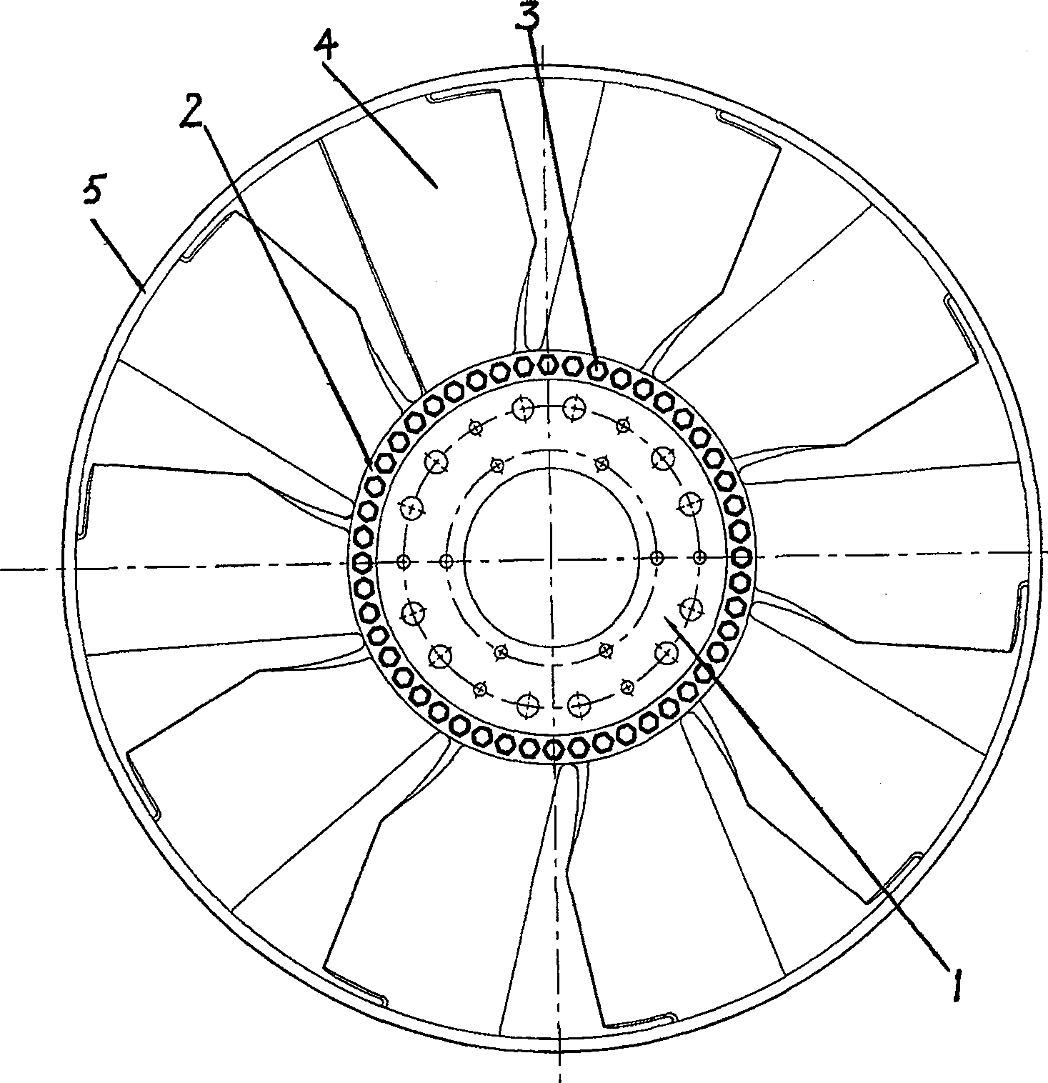
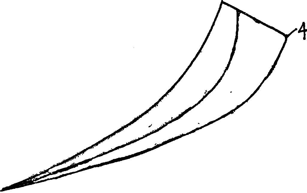
[0014] Embodiment one: see figure 1 and figure 2 , an automobile engine cooling fan, comprising a tray 1, a hub 2, ribs 3, and blades 4, the impeller is composed of the tray 1, the hub 2, and blades 4, the blades 4 are airfoil-shaped cross-section blades, and the blades 4 and the hub 2 are integrally formed , the ratio of the chord length between the inner and outer diameters of each blade 4 is 1:1.1, the angle between the line of the center of gravity of each section of the blade 4 and the radial straight line is 5°, and the projection distance of the line of the center of gravity of each section of the blade 4 on the rotation axis is controlled At 2% of the diameter of the impeller, it is in the shape of space distortion, the connection between the blade 4 and the hub 2 adopts a circular arc transition, and the reinforcing rib 3 is a honeycomb reinforcing rib, and the honeycomb reinforcing rib is a regular hexagon. The vane 4 is connected with the guide ring 5 together.

Embodiment 2

[0015] Embodiment two: see figure 1 and figure 2 , an automobile engine cooling fan, comprising a tray 1, a hub 2, ribs 3, and blades 4, the impeller is composed of the tray 1, the hub 2, and blades 4, the blades 4 are airfoil-shaped cross-section blades, and the blades 4 and the hub 2 are integrally formed The ratio of the chord length between the inner and outer diameters of each blade 4 is 1:1.5, the angle between the line of the center of gravity of each section of the blade 4 and the radial straight line is 25°, and the projection distance of the line of the center of gravity of each section of the blade 4 on the rotation axis is controlled At 8% of the diameter of the impeller, it is in the shape of space distortion, and the connection between the blade 4 and the hub 2 adopts a circular arc transition. Others are the same as embodiment one.

Embodiment 3

[0016] Embodiment three: see figure 1 and figure 2 , an automobile engine cooling fan, comprising a tray 1, a hub 2, ribs 3, and blades 4, the impeller is composed of the tray 1, the hub 2, and blades 4, the blades 4 are airfoil-shaped cross-section blades, and the blades 4 and the hub 2 are integrally formed , the ratio of the chord length between the inner and outer diameters of each blade 4 is 1:1.3, the angle between the line of the center of gravity of each section of the blade 4 and the radial straight line is 15°, and the projection distance of the line of the center of gravity of each section of the blade 4 on the rotation axis is controlled At 5% of the diameter of the impeller, it is in the shape of space distortion, and the connection between the blade 4 and the hub 2 adopts a circular arc transition. Others are the same as embodiment one.


PUM


Abstract

A vehicle engine cooling fan is disclosed. The invention comprises a tray, a wheel hub and a reinforced rib, and blades. The impeller comprises a tray, a wheel hub, and blades. the blades are airfoil shaped cross section blades, the blades and the wheel hub are formed an integral body, the chord length ratio of the inner and the outer diameters of each blade is between 1:1.1 to 1:1.5, the included angle of each cross section gravity line and the radial straight line of the blades is between 5 degrees to 25 degrees, the projection distance on the rotating axle of each cross section gravity line of the blades is controlled between 2% to 8% of the impeller diameter, the projection distance presents a space twisted shape, and the arc transition is adopted at the connection of the blade and the wheel hub. The reinforced rib is a honeycomb-shaped reinforced rib, and the honeycomb-shaped reinforced rib is of a regular hexagon hexagonal shape. The blades and the diversion ring are connected together. The efficiency is high, the noise is small, the slip flow can not easily occur at the tail part, and the service life is long.

Description

technical field [0001] The invention relates to an automobile engine cooling fan. Background technique [0002] With the rapid development of national economic construction, the use of automobiles is becoming more and more popular. The heat dissipation system is a very important part of the car cooling system. The performance of the cooling fan directly leads to the running effect of the car engine. Low-noise, high-efficiency fans dedicated to cooling require compact size, light weight, and good aerodynamic performance and acoustic indicators. There are generally two types of fans for automobiles, one is an open fan, and the other is an annular fan. [0003] The open cooling fan is mainly composed of a tray, a hub, and blades. Annular fans are mainly composed of trays, hubs, blades, and guide rings. The blades of the annular fan are connected with the guide ring, which reduces the weight of the fan, increases the rigidity, reduces the deformation of the fan, has good st...

Claims


Application Information

Patent Timeline
Patent Type & Authority Patents(China)
IPC IPC(8): F04D29/38
Inventor 丁维福
Owner WENZHOU YILONG AUTO PARTS CO LTD
Why Eureka
Try Eureka