Flame tube with novel cooling structure

A technology of cooling structure and flame tube, which is applied in the direction of combustion method, combustion chamber, combustion equipment, etc., can solve problems such as stress concentration, inability to meet gas volume requirements, and flame tube cracks.

Active Publication Date: 2021-07-30
AECC HUNAN AVIATION POWERPLANT RES INST
View PDF7 Cites 1 Cited by
  • Summary
  • Abstract
  • Description
  • Claims
  • Application Information

AI Technical Summary

Problems solved by technology

[0008] (1) These types of cooling structures need to process hundreds of thousands of cooling hole structures at different positions on the surface of the flame tube. The wall of the cooling hole is thin and easy to form stress concentration, which is one of the causes of cracks in the flame tube ;
[0009] (2) The existing cooling structures all require a large amount of cooling air, and basically most of the air is only used to cool the wall of the flame tube, and does not participate in the combustio

Method used


Image

  • Flame tube with novel cooling structure
  • Flame tube with novel cooling structure
  • Flame tube with novel cooling structure

Examples


Embodiment Construction

[0046] The following will clearly and completely describe the technical solutions in the embodiments of the present invention with reference to the accompanying drawings in the embodiments of the present invention. Obviously, the described embodiments are only some, not all, embodiments of the present invention. Based on the embodiments of the present invention, all other embodiments obtained by persons of ordinary skill in the art without making creative efforts belong to the protection scope of the present invention.

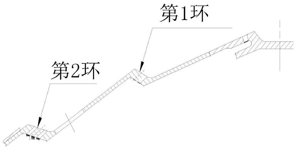
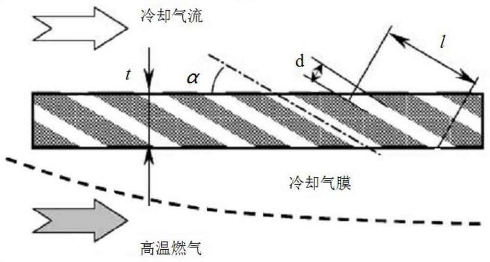
[0047] see Figure 6-14 , in an embodiment of the present invention, a novel cooling structure of the flame tube includes a combustor casing 1, a flame tube body 3 and a large elbow 4 are arranged inside the combustor casing 1, and the combustor casing One side of 1 is provided with an inlet diffuser 2, and the interior of the combustion chamber casing 1 is provided with an overlapping section 5 between the flame cylinder body 3 and the large elbow 4, and the ...


PUM

PropertyMeasurementUnit
Wall thickness sizeaaaaaaaaaa

Abstract

The invention discloses a flame tube with a novel cooling structure. The flame tube comprises a combustion chamber casing, wherein a flame tube body and a large elbow are arranged in the combustion chamber casing, an inlet diffuser is arranged on one side of the combustion chamber casing, a lap joint section is arranged in the combustion chamber casing and between the flame tube body and the large elbow, an outer ring main combustion mixing hole is formed in an outer ring of the flame tube body, a head swirler mounting hole is formed in a head ring of the flame tube body, an inner ring main combustion mixing hole is formed in an inner ring of the flame tube body, the flame tube body comprises the outer ring, the head ring, the inner ring and a small elbow, the outer ring, the head ring, the inner ring and the small bent pipe of the flame tube body are of an integrated structure, and zigzag small-aperture circular cooling channels are formed in the wall faces of the outer ring, the head ring, the inner ring and the small elbow of the flame tube body and the wall face of the large elbow respectively, so that the number of holes formed in the wall faces is greatly reduced, cracks of the holes are reduced, and the service life of the flame tube body is prolonged.

Description

technical field [0001] The invention belongs to the technical field of aero-engines, in particular to a flame tube with a novel cooling structure. Background technique [0002] With the continuous improvement of the thrust-to-weight ratio (power-to-weight ratio) of aero-engines, the aero-engine combustors will develop in the direction of high temperature rise and high heat capacity in the future, and the thermal protection problem of the combustors will become increasingly severe. On the one hand, the high-temperature combustion chamber requires a substantial increase in the proportion of air involved in combustion, and the amount of air available for cooling will inevitably decrease; on the other hand, in order to improve the engine cycle efficiency and reduce fuel consumption, the boost ratio of the compressor will also be greatly increased. The temperature at the combustion chamber inlet increases, which in turn reduces the cooling potential of the cooling air. Under the...

Claims


Application Information

Patent Timeline
IPC IPC(8): F23R3/42
CPCF23R3/42
Inventor 黎超超曾琦万卜铭陈江唐超胡畅陈晓龙刘瑶王良张靖旋李佳玲
Owner AECC HUNAN AVIATION POWERPLANT RES INST
Why Eureka
Try Eureka