Method for evaluating micro-gravity dual-axis gyrator

A gyroscope, microgravity technology, applied in the testing of machine/structural components, instruments, measuring devices, etc., can solve the problems that plague researchers, complex motion and force conditions, etc.

Inactive Publication Date: 2010-06-09
NAT SPACE SCI CENT CAS
View PDF0 Cites 4 Cited by
  • Summary
  • Abstract
  • Description
  • Claims
  • Application Information

AI Technical Summary

Problems solved by technology

However, due to the large number of adjustable motion parameters, the motion and stress of the test object in the gyrator are complicated. Therefore, how different parameter settings affect the motion of the test object has always been a problem that plagues researchers.

Method used


Image

  • Method for evaluating micro-gravity dual-axis gyrator
  • Method for evaluating micro-gravity dual-axis gyrator
  • Method for evaluating micro-gravity dual-axis gyrator

Examples


Embodiment Construction

[0076] The present invention will be described in detail below in conjunction with the accompanying drawings and specific embodiments.

[0077] 1) Establish a coordinate system and perform coordinate transformation

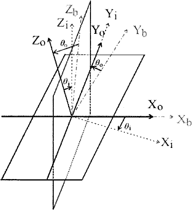
[0078] Establish base coordinate system, outer ring coordinate system and inner ring coordinate system, as attached figure 2 shown;

[0079] Assume that the base, outer ring and inner ring are denoted by subscripts b, o and i respectively, and according to the transformation principle under the rotating coordinate system, the direction cosine between the outer ring and the base is listed in Table 2 below;

[0080]

[0081] The direction cosine between the inner ring and the outer ring is shown in Table 3 below;

[0082]

[0083] From Table 2 and Table 3, Table 4 can be obtained, that is, the direction cosine between the inner ring and the base, as follows:

[0084]

[0085] 2) Parameter calculation

[0086] 2.1.1 Location

[0087] as attached Figur...


PUM


Abstract

The invention relates to a method for evaluating a micro-gravity dual-axis gyrator, the dual-axis gyrator consists of an inner ring and an outer ring, and the method for evaluating the micro-gravity dual-axis gyrator comprises the following steps: 11) carrying out physical modeling for the dual-axis gyrator; 12) establishing three coordinate systems of a base coordinate system, an inner ring coordinate system and an outer ring coordinate system, as shown in Figure 2, wherein the base coordinate system is a fixed coordinate system; 13) utilizing the rotating vector properties of the coordinatesystems for finally deriving an apparent gravity acceleration formula of an object, wherein apparent gravity acceleration is the projection of gravitational acceleration under the inner ring coordinate system, and the value is the vector sum of the acceleration and the gravitational acceleration produced by the rotation of the inner ring and the outer ring, and 14) utilizing the apparent gravity acceleration formula and a simulation platform for evaluating the effect of simulating micro-gravity of parameter settings according to parameters set by the micro-gravity dual-axis gyrator, if the obtained apparent gravity acceleration can achieve all rotating positions, the parameter settings can simulate the micro-gravity effect.

Description

technical field [0001] The invention relates to a biaxial gyrator for simulating biological microgravity effects, in particular to a method for evaluating a microgravity biaxial gyrator. Background technique [0002] With the development of the aerospace industry, the microgravity effect in space has gradually attracted the attention of scientific researchers. Substances such as organisms and materials will show some unique characteristics in a microgravity environment, which will drive the development of science and technology in related fields. Among them, the microgravity effect of biology is a hot spot in microgravity research. one. However, due to the complex space environment and high cost, many experiments cannot be carried out. Therefore, the use of ground experimental devices to simulate microgravity effects has become the first choice for many experiments. [0003] In the simulation of the biological weightlessness effect, the microgravity gyrator (Clinostat) is ...

Claims


Application Information

Patent Timeline
Patent Type & Authority Applications(China)
IPC IPC(8): G01M19/00G01M99/00
Inventor 王迪蒋远大张志远王鲁锋李维宁翟光杰
Owner NAT SPACE SCI CENT CAS
Why Eureka
Try Eureka