Light guide plate, backlight module, liquid crystal display device and electric equipment

A technology of liquid crystal display and backlight module, which is applied in mechanical equipment, lighting devices, lighting and heating equipment, etc., and can solve problems such as labor-intensive assembly hours and poor fitting of hooks

Inactive Publication Date: 2010-06-09
INNOLUX CORP
View PDF0 Cites 24 Cited by
  • Summary
  • Abstract
  • Description
  • Claims
  • Application Information

AI Technical Summary

Problems solved by technology

The backlight module 20 further includes a back shell 32 and a plastic frame 34, wherein the back shell 32 is combined with the plastic frame 34 to connect the light guide plate 22, the lamp tube 24, the U-shaped reflector 26, the optical film group 30 and The reflector 28 is fixed between the back shell 32 and the plastic frame 34. Therefore, when the backlight module 20 is assembled, it is usually necessary to design fixing methods such as hooks, which not only consume man-hours of manual assembly, but also often have the problem of poor fitting of the hooks.

Method used


Image

  • Light guide plate, backlight module, liquid crystal display device and electric equipment
  • Light guide plate, backlight module, liquid crystal display device and electric equipment
  • Light guide plate, backlight module, liquid crystal display device and electric equipment

Examples


Embodiment Construction

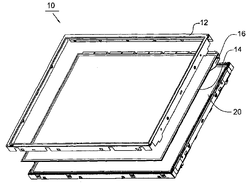
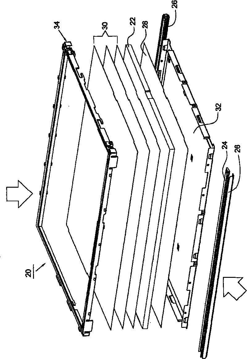
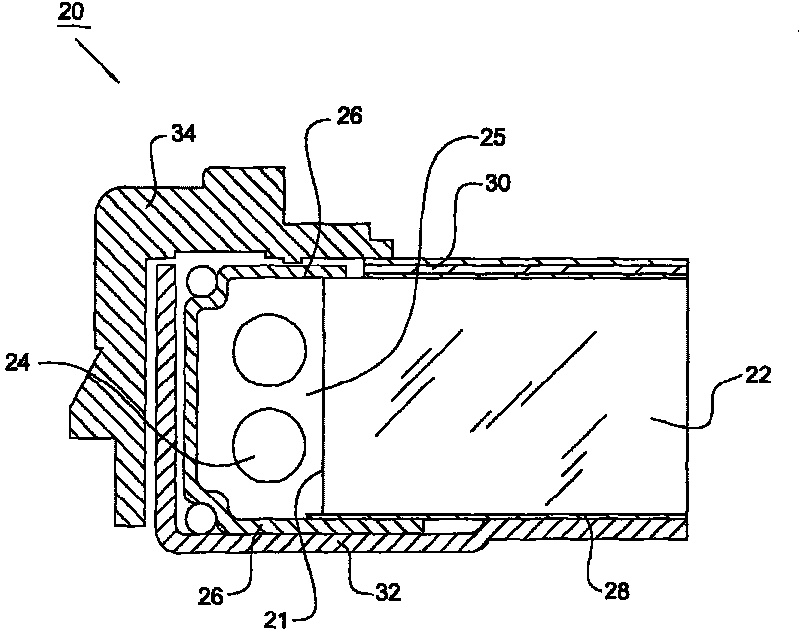
[0058] refer to Figure 4 and5 , which shows a backlight module 120 according to an embodiment of the present invention. The backlight module 120 includes a light guide plate 122 , a light source unit 124 , an optical film set 130 and a reflector 128 . The light guide plate 122 has a top surface 150 , a first bottom surface 152 , two first side surfaces 154 and two first side surfaces 156 . The first bottom surface 152 is opposite to the top surface 150 , and the two first side surfaces 154 and the two first side surfaces 156 are connected to the top surface 150 and the first bottom surface 152 .

[0059] The light guide plate 122 includes a first accommodating space 163 disposed on the top surface 150 for fixing a liquid crystal panel. The first accommodating space 163 includes four second sides 164b, a first opening 164a and a second bottom surface 164c, wherein the second side 164b connects the top surface 150 and the second bottom surface 164c, and the second side 164b i...


PUM


Abstract

The invention relates to a light guide plate which comprises a first accommodating space, a second accommodating space and a third accommodating space, wherein the first accommodating space is used for fixing a liquid crystal panel; the second accommodating space is used for configuring an optical membrane set; and the third accommodating space is used for configuring a light source unit. Due to the functions of the first accommodating space, the second accommodating space and the third accommodating space of the light guide plate, the accommodating functions of a back shell and a rubber frame of a known backlight module can be replaced, and the liquid crystal panel, the optical membrane set and the light source unit are directly accommodated on the light guide plate, thus the back shell and the rubber frame can be cancelled so as to ensure that the thickness of the backlight module can become thinner. Meanwhile, the design of a clamping hook can be cancelled, thus the backlight module can be simpler to assemble and has lower cost, and the automation of the backlight module can also be introduced.

Description

technical field [0001] The present invention relates to a liquid crystal display device, more particularly to a backlight module, the functions of the first, second and third accommodating spaces of the light guide plate can directly connect the liquid crystal panel, the optical film group And the light source unit is placed on the light guide plate. Background technique [0002] With the advancement of electronic technology, especially the popularity of portable electronic products in daily life, there is an increasing demand for displays that are thin, light, small, and low in power consumption. Due to the advantages of low power consumption, low heat generation, and light weight, liquid crystal displays (Liquid Crystal Displays; LCDs) are often used in such electronic products and have gradually replaced traditional cathode ray tube displays. [0003] refer to figure 1 , the known liquid crystal display device 10 mainly includes a front frame 12 , a liquid crystal panel...

Claims


Application Information

Patent Timeline
Patent Type & Authority Applications(China)
IPC IPC(8): G02B6/00F21V8/00G02F1/13357F21V17/00
Inventor 万建明林健佑
Owner INNOLUX CORP
Why Eureka
Try Eureka