
Electric connecting anchor clamp with measurable force

A technology of power connection and fittings, applied in the direction of measuring force, measuring devices, cable suspension devices, etc., can solve the problems of heavy workload, on-site installation, troublesome replacement, and does not include processing circuits, etc., to save costs and reduce difficulties Effect

Inactive Publication Date: 2010-06-09
STATE GRID SICHUAN ELECTRIC POWER CORP ELECTRIC POWER RES INST
View PDF0 Cites 4 Cited by
  • Summary
  • Abstract
  • Description
  • Claims
  • Application Information

AI Technical Summary

Problems solved by technology

[0005] 1. Due to the need to design specific brackets for different iron towers, the workload is heavy, and at the same time, it is troublesome to install and replace on site
[0006] 2. Due to the change of the structure of the insulator string, it may lead to changes in the safety distance and structural strength, resulting in serious consequences
[0007] At the same time, these force sensors are all non-intelligent sensors, and they do not contain processing circuits, let alone algorithms for force change feature analysis, resulting in too single information extracted from them

Method used


Image

  • Electric connecting anchor clamp with measurable force
  • Electric connecting anchor clamp with measurable force

Examples


Embodiment 1

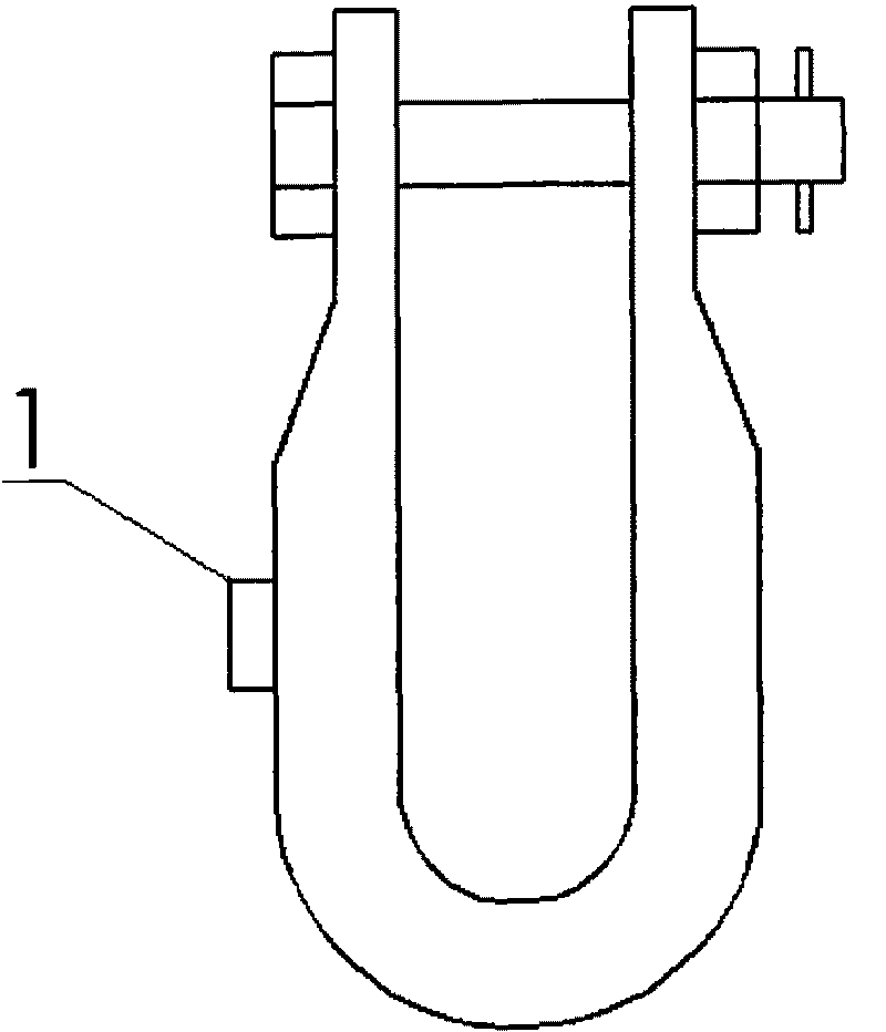
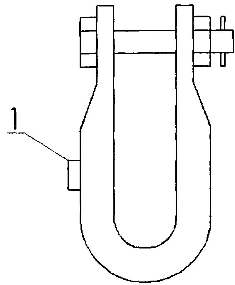
[0021] Two pieces of resistance strain gauges are pasted on the ring-chain series connection fittings such as U-shaped hanging rings where the stress is balanced (relatively flat). When the U-shaped hanging rings are subjected to tension, deformation will occur, and the deformation will be sensed by the resistance strain gauges Measurement. By processing the change of resistance through the circuit, the magnitude of the pulling force can be obtained.

[0022] In order to protect the patch, a protective body can be made to protect the patch and lead out the wires. In the follow-up processing circuit, a compensation can be made for the material and temperature of the fitting through a circuit or a mathematical method to make the measurement more accurate (in fact, the difference in force before and after the actual icing accident is about tons, determined by From this we know that reliability is the most important), through the 12-bit AD conversion that comes with the STM32 pro...

Embodiment 2

[0025] Paste four semiconductor strain gauges on the plate-plate series connection fittings such as the stress equalization position (relatively straight) on the parallel hanging plate. When the hanging plate is stressed, the strain gauge will sense the force.

[0026] Through wires, the information will be forwarded to a monitoring control box located nearby, and the subsequent processing will be completed by the monitoring control box.

Embodiment 3

[0028] Paste a piece of resistance strain gauge on the stress equalization place (relatively flat place) of the ball-socket series connecting fittings such as the ball joint ring. When the hanging ring is stressed, the strain gauge will sense the force.

[0029] Through circuit processing, the strain is converted into a 4-20mA signal, which represents the force of 0-10 tons. Through the wire, the information will be transmitted to a nearby monitoring control box, and the subsequent processing is completed by the monitoring control box.


PUM


Abstract

The invention provides an electric connecting anchor clamp with measurable force and relates to an electric connecting anchor clamp. The electric connecting anchor clamp with measurable force comprises an electric connecting anchor clamp and a processing circuit receiving output signal of a sensing element, wherein the sensing element is a strain meter or strain gauge, or one or more strain meters or strain gauges which are bonded to the strain balancing part of the electric connecting anchor clamp. On the premise of not changing the structure of the original insulator string, the electric connecting anchor clamp can achieve the effect of monitoring the gravity and the gravity change of the electric transmission line.

Description

technical field [0001] The invention relates to an electric power fitting, in particular to a power connecting fitting, on which a stress sensitive element is pasted and can measure the force acting on it. Background technique [0002] Current power connection fittings do not function as force sensors and cannot measure the magnitude of the force applied to them. Due to the icing of power transmission lines and other reasons, it is necessary to monitor the force of power transmission lines on the tower through insulator strings in real time to obtain information on the thickness of ice. At present, there are usually two solutions: one is to install a specific bracket on the tower, and install the force sensor on the bracket; the other is to design a special insulator structure, and place the force sensor as a non-standard fitting on the insulator string to go. [0003] Of course, there are also some indirect measurement methods, such as measuring the change of the inclinat...

Claims


Application Information

Patent Timeline
IPC IPC(8): H02G7/05G01L1/22
Inventor 曹永兴顾海李海峰
Owner STATE GRID SICHUAN ELECTRIC POWER CORP ELECTRIC POWER RES INST
Learn More