Unpowered whirling cylinder sand and sludge removing machine

A cyclone and power technology, applied in the field of unpowered cyclone sand and sludge removal machines, can solve the problems of power consumption and low sedimentation rate, and achieve increased outflow speed, high sand settling efficiency, and sand settling speed. quick effect

Inactive Publication Date: 2010-06-16
无锡强工机械工业有限公司
View PDF0 Cites 4 Cited by
  • Summary
  • Abstract
  • Description
  • Claims
  • Application Information

AI Technical Summary

Problems solved by technology

[0004] At present, the sedimentation tank and cyclone desanding machine (cyclone separator) commonly used in China, and the general cyclone desander (cyclone separator) have the disadvantages of power consumption and low sedimentation rate.

Method used


Image

  • Unpowered whirling cylinder sand and sludge removing machine
  • Unpowered whirling cylinder sand and sludge removing machine
  • Unpowered whirling cylinder sand and sludge removing machine

Examples


Embodiment Construction

[0014] The present invention will be further described below in conjunction with specific drawings and embodiments.

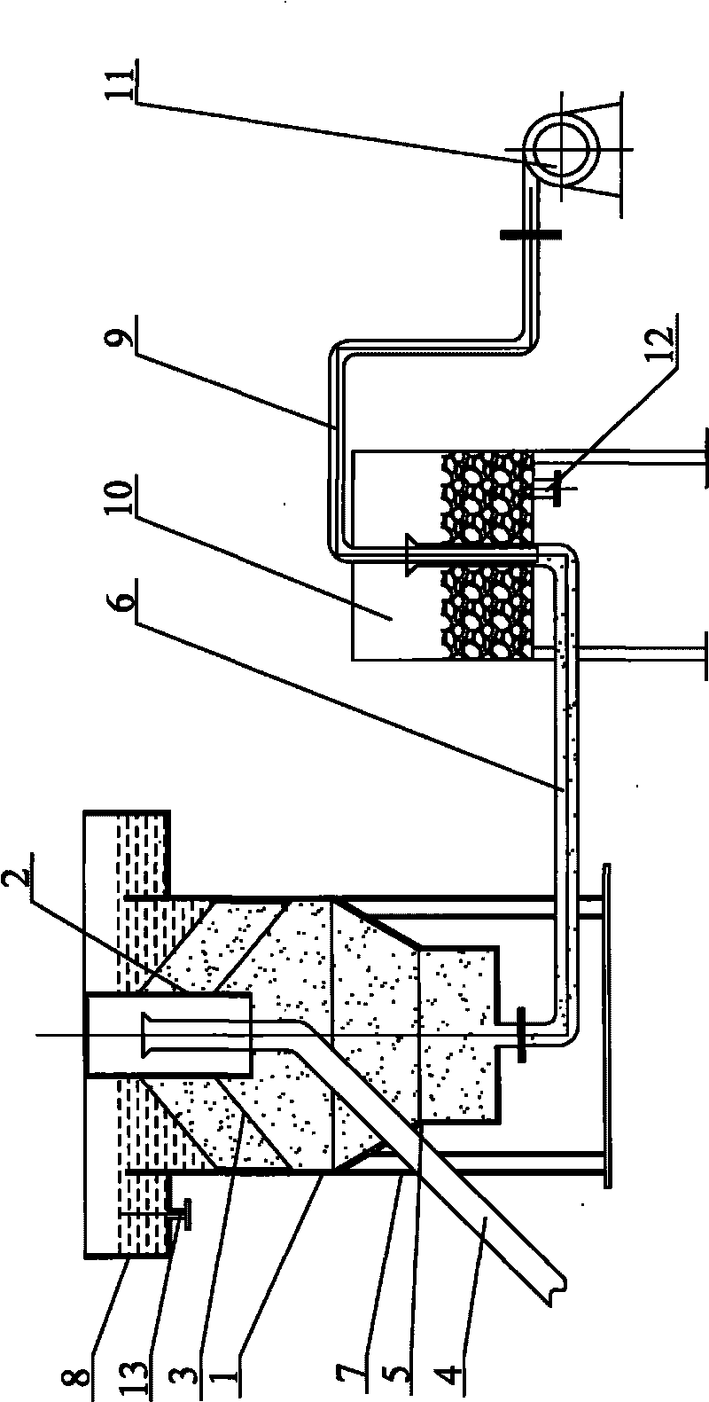
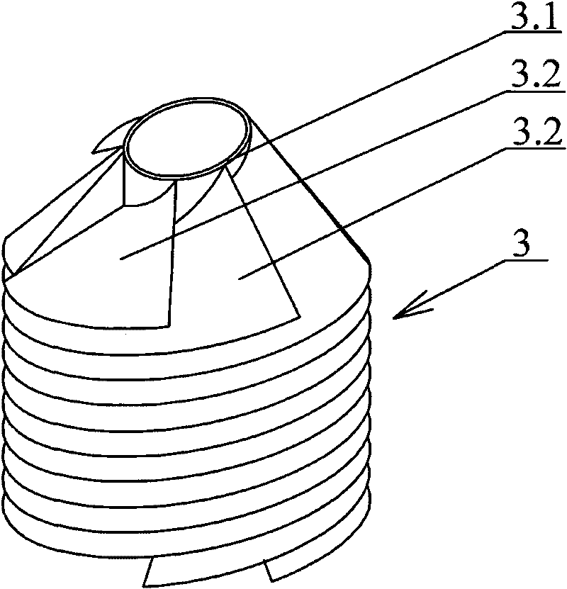
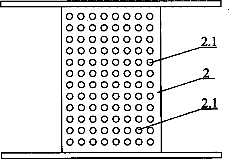
[0015] As shown in the figure: the unpowered cyclone cylinder sand and sludge removal machine includes a processing cylinder 1, a mud input pipe 4 and a slurry output pipe 6, a compressed gas conduit 9, a slurry storage container 10 and an air pump 11. A vortex filter separator 3 is installed on the inner wall of the upper part of the treatment cylinder 1, and a coarse slurry slag collection tank 5 is installed in the treatment cylinder 1 below the vortex filter separator 3, and the output end of the mud input pipe 4 is separated from the vortex filter. The water inlet of device 3 conveys muddy water, is equipped with slurry output pipe 6 on the groove bottom of coarse slurry slag collecting tank 5, and the discharge end of slurry output pipe 6 stretches in the slurry storage container 10, and the compressed air conduit 9 The input end is connected with the air...


PUM


Abstract

The invention relates to an unpowered whirling cylinder sand and sludge removing machine. The machine comprises a treatment cylinder, a slurry input pipe, a reject output pipe, a compressed gas conduit, a reject storage vessel and a gas pump, wherein a vortex filter separator is arranged on the inner wall of the upper section of the treatment cylinder; a coarse reject collecting tank is arranged in the treatment cylinder under the vortex filter separator; the output end of the slurry input pipe feeds slurry water to a water inlet of the vortex filter separator; a reject output pipe is arranged at the bottom of the coarse reject collecting tank; the discharge end of the reject output pipe extends into the reject storage vessel; and the input end of the compressed gas conduit is connected with the gas pump, and the output end of the compressed gas conduit is inserted into the output section of the reject output pipe. The machine saves energy, and ensures that the sewage automatically rotates, whirls and accelerates; the sewage whirling forms vortex speed difference, which is convenient to deposit sand and eliminate external interference, and has high sand depositing efficiency; and the machine also improves the outflow speed of the sewage so as to realize the function of sand and water separation.

Description

technical field [0001] The invention relates to sewage and sludge treatment equipment, in particular to a non-powered swirl tube desand and sludge remover. Background technique [0002] In the domestic sewage and industrial wastewater, the sewage collected by various channels is involved in a large amount of mud and sand, which brings great resistance and difficulty to the circulation of sewage and the process of sewage treatment. A very important part of the initial stage. [0003] The main purpose of sand settling and sand removal is to use the simplest means and the most economical method to achieve the effect of sand settling and sand removal as much as possible, so that the sewage with reduced sand content can enter the various processes of sewage treatment smoothly, so as to ensure that the process of sewage treatment The smooth progress of the process, thereby improving the quality of sewage treatment. [0004] At present, the sedimentation tank and cyclone desandin...

Claims


Application Information

Patent Timeline
IPC IPC(8): B01D21/26
Inventor 强光初
Owner 无锡强工机械工业有限公司
Why Eureka
Try Eureka