Supercharge Your Innovation With Domain-Expert AI Agents!

Turning tool cutter row device of combined working machine tool of milling machine

A compound processing and tool array technology, applied in the direction of tool holders, etc., can solve the problems of inability to realize automatic clamping and tool changing of turning tools, reduce the production efficiency of milling and turning machine tools, and affect the degree of automation of milling and turning machine tools. , to achieve the effect of easy disassembly and assembly, simple and unique positioning method

Inactive Publication Date: 2010-06-16
黑龙江光大数控机床有限责任公司
View PDF0 Cites 5 Cited by
  • Summary
  • Abstract
  • Description
  • Claims
  • Application Information

AI Technical Summary

Problems solved by technology

[0003] The purpose of the present invention is to provide a turning tool row device for a milling and turning machine tool to solve the problem that the existing milling and turning machine tools cannot realize automatic clamping and changing of turning tools when the milling process and the turning process are switched. Knives affect the automation of milling and turning machine tools, thereby reducing the production efficiency of milling and turning machine tools

Method used


Image

  • Turning tool cutter row device of combined working machine tool of milling machine
  • Turning tool cutter row device of combined working machine tool of milling machine
  • Turning tool cutter row device of combined working machine tool of milling machine

Examples


specific Embodiment approach 1

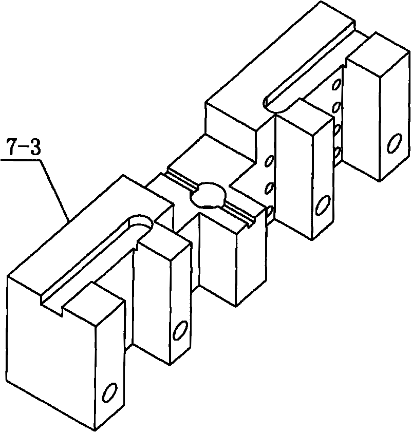
[0007] Specific implementation mode one:, as Figure 3-5 As shown, the turning tool row device of the milling and turning compound processing machine tool described in this embodiment includes a tool row locator 7-1, a knife handle 7-2 and a tool row main body 7-3, and the tool row locator 7-1 The profile is cylindrical, the profile of the knife handle 7-2 is conical, and the knife row main body 7-3 has four vertical grooves 7-3-1 on the side along the length direction, and the four vertical grooves 7-3-1 is used to place four turning tools for processing the outer circle, and a knife hole 7 is opened on the same side of the knife row main body 7-3 on both sides of the vertical groove 7-3-1 at the end -3-2, four knife holes 7-3-2 are used to place four turning tools for processing inner holes; knife handle 7-2 is arranged on the middle part of the upper end surface of knife row main body 7-3, and knife handle 7-2 The large end of the blade is connected to the upper end surfac...

specific Embodiment approach 2

[0009] Specific implementation mode two: as Figure 3-5 As shown, the turning tool row device 7 of this embodiment also includes two positioning keys 7-4, and a positioning keyway 7-3-3 is respectively opened on the two ends of the upper end surface of the tool row main body 7-3, and the tool row positioning The lower end face of device 7-1 is connected with the upper end face of knife row main body 7-3 by the positioning key 7-4 that is contained in the positioning key groove 7-3-3. The positioning keyway 7-3-3 is parallel to the Y-axis (sliding saddle 1) of the machine tool. Through the contact between the upper end surface of the 7-4 positioning key and the bottom surface of the 7-1 upper keyway, the impact force of turning on the milling spindle is reduced, thereby prolonging the service life of the milling machine spindle. Other components and connections are the same as those in the first embodiment.

specific Embodiment approach 3

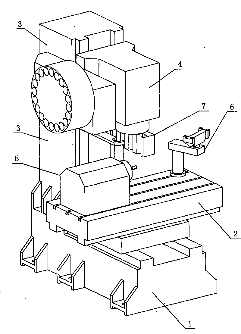
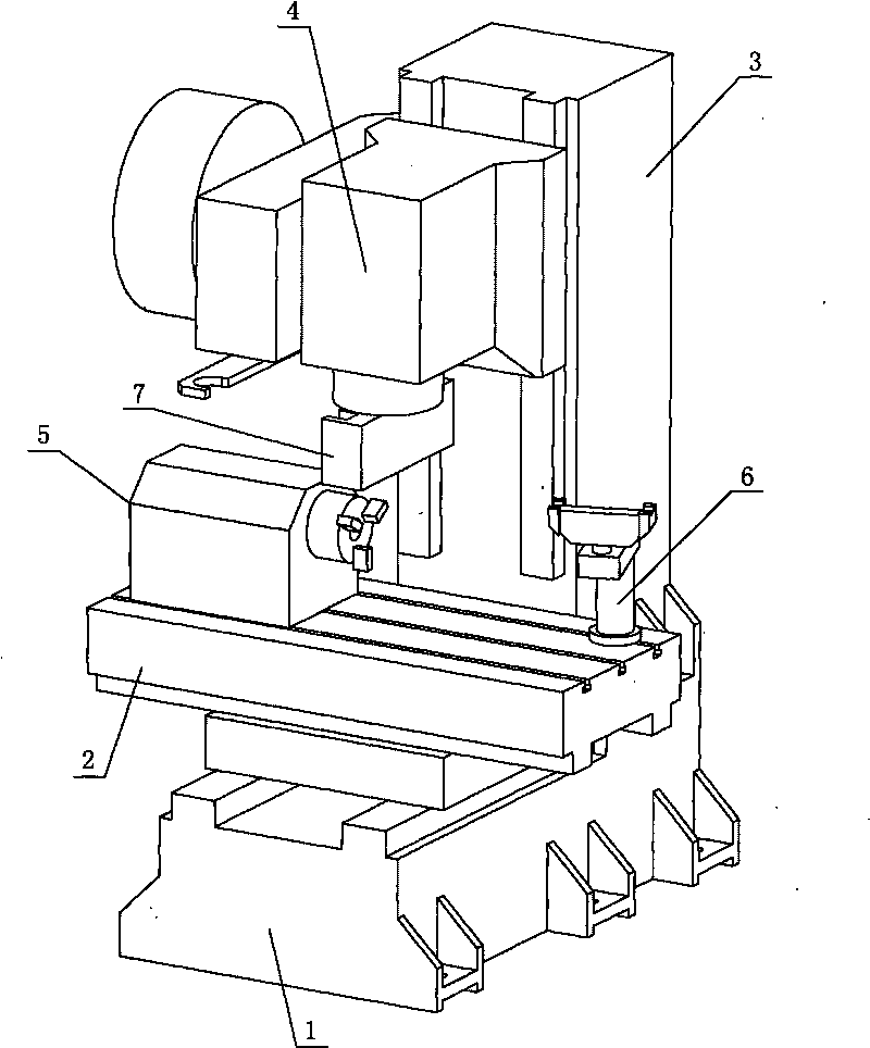
[0010] Specific implementation mode three: as Figure 1~2 As shown, the present embodiment is equipped with the milling-turning compound processing machine tool of the present invention, and the compound processing machine tool comprises a milling machine main body, and the milling machine main body comprises a saddle 1, a workbench 2, a column 3 and a headstock 4, and the workbench 2 Horizontally located above the saddle 1 and the two are arranged in a cross shape, the column 3 is located at the rear end of the table 2 and the lower end of the column 3 is connected to the saddle 1, the headstock 4 is located above the table 2 and the headstock 4 is connected to the column 3 sliding connection; the compound processing machine tool also includes a lathe spindle assembly 5, a lathe tool changing mechanism 6 and a turning tool row device 7, the lathe spindle assembly 5 is arranged on the left end of the workbench 2 and is slidably connected with the workbench 2, The lathe tool ch...


PUM


Abstract

The invention discloses a turning tool cutter row device of a combined working machine tool of a milling machine, which relates to a turning tool cutter row device and solves the problems that the existing combined working machine tool of the milling machine cannot realize automatic clamping and changing of turning tool cutters during the conversion of a milling process step and a turning process step so that the automation degree of the combined working machine tool of the milling machine is influenced and the production efficiency of the combined working machine tool of the milling machine is reduced. The lateral surface, along the length direction, of a cutter row main body is provided with four vertical grooves; the same lateral surface, on two sides of the vertical grooves positioned at the end part, of the cutter row main body is provided with a cutter hole; a cutter handle is arranged in the middle of the upper end face of the cutter row main body; the big end of the cutter handle is connected with the upper end face of the cutter row main body; a cutter row positioner is arranged on the upper part of the cutter row main body; the cutter handle is positioned in an inner cavity of the cutter row positioner; and the lower end face of the cutter row positioner is connected with the upper end face of the cutter row main body. The turning tool cutter row device changes the turning tool changing mode and the turning tool fixing mode of existing like products, and improves the production efficiency.

Description

technical field [0001] The invention relates to a turning tool row device, in particular to a turning tool row device of a milling and turning compound processing machine tool, belonging to the field of metal cutting numerical control processing equipment. Background technique [0002] The milling and turning compound processing machine tool integrates the milling function and the turning function, which reduces the footprint of the processing machine tool, reduces the number of clamping and positioning times for processing a workpiece, and saves the time required for process conversion; the milling and turning compound Due to the above advantages, processing machine tools have been widely used in metal cutting. However, the existing milling-turning compound processing machine tool is not equipped with a turning tool row device, so that when the milling process and the turning process are switched, the intensification and automatic control of the connection between the milli...

Claims


Application Information

Patent Timeline
IPC IPC(8): B23B29/24
Inventor 董海滨马怀念王立平余锦坤
Owner 黑龙江光大数控机床有限责任公司
Features
  • R&D
  • Intellectual Property
  • Life Sciences
  • Materials
  • Tech Scout
  • Unparalleled Data Quality
  • Higher Quality Content
  • 60% Fewer Hallucinations
Learn More