Laser welding device

A technology of laser welding and laser beam welding, applied in the field of devices used for welding, can solve the problems of limitation, easy generation of welding pores X-rays, pollution of the structure and size of the weld seam, etc., so as to reduce the volume and density, and eliminate the laser welding pores. , Increase the effect of weld penetration

Inactive Publication Date: 2010-06-16
HARBIN INST OF TECH
View PDF0 Cites 25 Cited by
  • Summary
  • Abstract
  • Description
  • Claims
  • Application Information

AI Technical Summary

Problems solved by technology

[0004] The purpose of the present invention is to solve the problems that welding pores are easily produced during laser welding of metal materials, X-ray pollutio

Method used


Image

  • Laser welding device
  • Laser welding device
  • Laser welding device

Examples


specific Embodiment approach 1

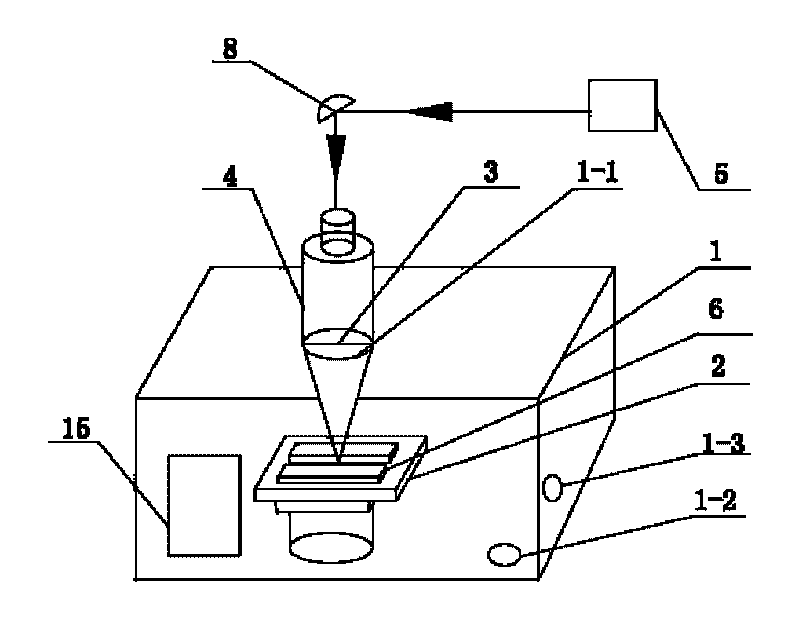
[0010] Specific implementation mode one: combine figure 1 Describe this embodiment, the device of this embodiment comprises workbench 2, focusing lens 3, laser beam welding torch head 4, laser 5 and at least one reflector 8, the light that described laser 5 outputs is reflected to by at least one reflector 8. In the laser input port of the laser beam welding gun head 4, the device also includes a vacuum chamber 1, the workbench 2 is installed in the vacuum chamber 1, and the upper wall of the vacuum chamber 1 is provided with a first through hole 1-1 , and the first through hole 1-1 is set corresponding to the workbench 2, the workpiece 6 is set on the workbench 2, and the head of the laser beam welding torch head 4 passes through the first through hole 1-1 and is set in a vacuum In the chamber 1, the laser beam welding gun head 4 is airtightly connected with the first through hole 1-1, the focusing lens 3 is installed in the laser beam welding gun head 4 and the focusing lens...

specific Embodiment approach 2

[0011] Specific implementation mode two: combination figure 1 Describe this embodiment, the laser 5 of this embodiment is CO2 laser, YAG laser, semiconductor laser or fiber laser, wherein the model of fiber laser is IPGYLR-20000 or IPGYLR-5000, CO 2 The model of the laser is DC030, the model of the YAG laser is HL2006D, DP020HX or DS 015HQ, and the model of the semiconductor laser is DL-028Q or DL-031Q. Other components and connections are the same as those in the first embodiment.

specific Embodiment approach 3

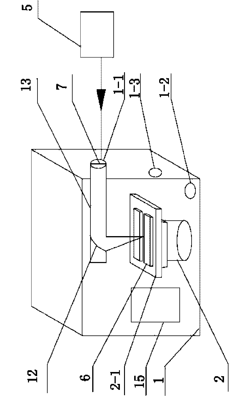
[0012] Specific implementation mode three: combination figure 2 Describe this embodiment, the device of this embodiment comprises workbench 2, laser 5, planar lens 7, reflective focusing lens 12 and reflective focused laser beam welding torch head 13, described reflective focused laser beam welded torch head 13 is Right-angled shape, the reflective focusing lens 12 is installed on the mirror holder at the 90 ° corner in the reflective focused laser beam welding gun head 13, the device also includes a vacuum chamber 1, and the workbench 2 is installed in the vacuum chamber 1 Inside, the side wall of the vacuum chamber 1 is provided with a first through hole 1-1, and the central axis of the first through hole 1-1 is arranged parallel to the upper table surface 2-1 of the workbench 2, and the workpiece 6 is arranged On the upper table 2-1 of the workbench 2, the reflective focused laser beam welding torch head 13 is arranged in the vacuum chamber 1, and the tail of the reflectiv...


PUM


Abstract

The invention relates to a laser welding device and aims to solve the problem that welding air holes are apt to be generated in laser welding of a metal material and the problem that welding by a vacuum electron beam causes X-ray pollution and limits the structure and size of weld joints to a certain degree. The invention adopts a scheme I that a laser beam welding gun head is in closed connected with both a first through hole and a focusing lens, a scheme II that a reflective focusing laser beam welding gun head is in sealed connection with both a first through hole and a flattening lens and is arranged relative to a laser arranged outside a vacuum room, and a scheme III that a laser beam welding gun head is connected with a laser, arranged relative to a worktable below and fixed on an arm of a welding robot arranged in an vacuum room. The device is used for laser welding.

Description

technical field [0001] The invention relates to a device for welding. Background technique [0002] In recent years, with the improvement of the industrialization of lasers and the emergence of new lasers, the feasibility study and application speed of laser welding technology in aerospace, aircraft, shipbuilding and other industrial fields have increased rapidly. However, due to the inevitable occurrence of pores or chain pores during laser welding, especially for thick plates or metals with strong chemical activity, such as beryllium and zirconium, the problem of pores is more serious when laser welding is used, which greatly limits The application of laser welding technology in aerospace, nuclear industry, national defense and other fields that require stricter weld quality. Therefore, laser welding porosity has become one of the main technical bottlenecks restricting the application of laser welding. [0003] For the problem of laser welding porosity, although vacuum e...

Claims


Application Information

Patent Timeline
IPC IPC(8): B23K26/20B23K26/12B23K26/24
Inventor 陈彦宾雷正龙陶汪李俐群李福泉
Owner HARBIN INST OF TECH
Why Eureka
Try Eureka