Drawing wire type serial mechanical arm

A manipulator and wire-pulling technology, applied in the field of serial manipulator structure, can solve the problems of large and complex parallel manipulator structure, unsuitable miniaturization, cost reduction and energy consumption, etc. The effect of small size and few additional devices

Inactive Publication Date: 2010-06-16
SOUTH CHINA UNIV OF TECH
View PDF0 Cites 49 Cited by
  • Summary
  • Abstract
  • Description
  • Claims
  • Application Information

AI Technical Summary

Benefits of technology

This patented technology allows for better performance and functionality than previous designs due to its unique design and compact construction. It uses an actuator (drive) placed inside or outside the robot's main body instead of just being connected directly to the driving unit. A pulling force from this external source helps move objects around without causing any resistance when they are located near them. Additionally, there may also include extra components like motors added between the two ends of the robot itself to make it easier to bend and compress materials. Overall, these technical improvements improve the overall functioning and efficiency of robots used today compared to older methods such as those described earlier.

Problems solved by technology

Technological Problem: Current methods for controllably moving robots use heavy duty actuator systems like hydraulic or electric cylinders, but these require extra equipment attached near their ends, making them bulky and expensive. To address this issue, there proposes an alternative approach called Power Delivery Parallel Mechanism (PDMP). Instead of adding more components to increase its strength without reducing its performance, PDPM uses tensile force instead of pulling forces to transfer power between two parts connected together. By doing so, the system becomes lighter while still being able to handle larger loads compared to previous designs. Additionally, PDLMS describes how the design allows for efficient operation even under severe environmental conditions where damage may occur due to collisions involving flying debris particles.

Method used


Image

  • Drawing wire type serial mechanical arm
  • Drawing wire type serial mechanical arm
  • Drawing wire type serial mechanical arm

Examples


Embodiment Construction

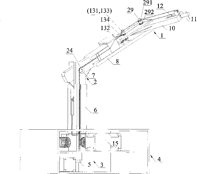
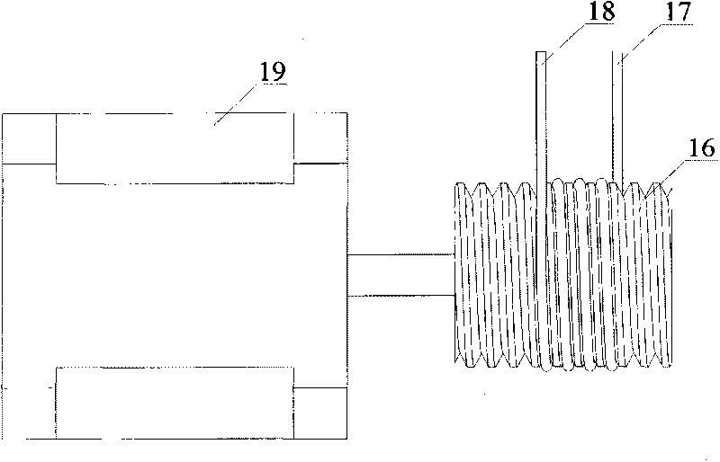
[0024] In this embodiment, the design of the drive box of the manipulator base: the motor winding mechanism is installed in the drive box of the manipulator base, and the winding mechanism is a spiral cylinder with a thread groove, which is directly installed on the rotating shaft of the motor, and is used for pulling and manipulating the pull wire. Movement; the rotation of the helical cylinder winding mechanism can make one end of the control cable wound in the spiral groove stretch, while the other end shortens, and the elongation and shortening of the two control lines are the same, so as to ensure that the control line maintains Tensioned state.

[0025] The design of each joint: including the wrist joint with 2 degrees of freedom, the elbow joint with 1 degree of freedom and the shoulder joint with 2 degrees of freedom.

[0026] The wrist joint includes a wrist joint shaft, a wrist joint rod and a wrist joint axial rotation mechanism. The wrist joint rod is connected wi...


PUM


Abstract

The invention relates to a drawing wire type serial mechanical arm which has two degrees of freedom (DOF) at wrist joint, one DOF at elbow joint and two DOFs at shoulder joint. The whole structure of the mechanical arm comprises a seat driving box, a joint rod and a joint drive mechanism. The driving motor of each DOF is mounted on the seat driving box of the mechanical arm, the motive power of the motor is transferred to the mechanical arm by manipulating the drawing wire, thus overcoming the influence of motor weight mounted on the mechanical arm to the carrying capacity and movement flexibility of the mechanical arm; forward and backward movement of each DOF of the mechanical arm can be realized by the forward and backward rotation of each detached driving motors, so that the drawing wire can maintain in tense state in the movement process, thus solving the unidirection property that means drawing but not compressing in the driving process; in the invention, the size and position of the pulley wheels are artfully configured, the effectively overcoming the defects such as small driving range and easy interference between wires in the driving process of parallel wires.

Description


Claims


Application Information

Patent Timeline
Owner SOUTH CHINA UNIV OF TECH
Why Eureka
Try Eureka