
Volume variable air conditioner compressor

An air-conditioning compressor and compressor technology, applied in the field of compressors, can solve the problems of changing the capacity of rotary compressors and energy waste, and achieve the effects of saving energy, reducing costs, and reducing thermal conductivity

Active Publication Date: 2018-10-26
江苏昊科汽车空调有限公司
View PDF10 Cites 0 Cited by
  • Summary
  • Abstract
  • Description
  • Claims
  • Application Information

AI Technical Summary

Problems solved by technology

At this time, when the difference between the ambient temperature and the preset standard temperature is not large, the compressor can operate in a small-capacity compression mode to save energy. However, the traditional rotary compressor cannot Differences between temperatures change the capacity of the rotary compressor, resulting in wasted energy

Method used


Image

  • Volume variable air conditioner compressor
  • Volume variable air conditioner compressor
  • Volume variable air conditioner compressor

Examples


Embodiment 1

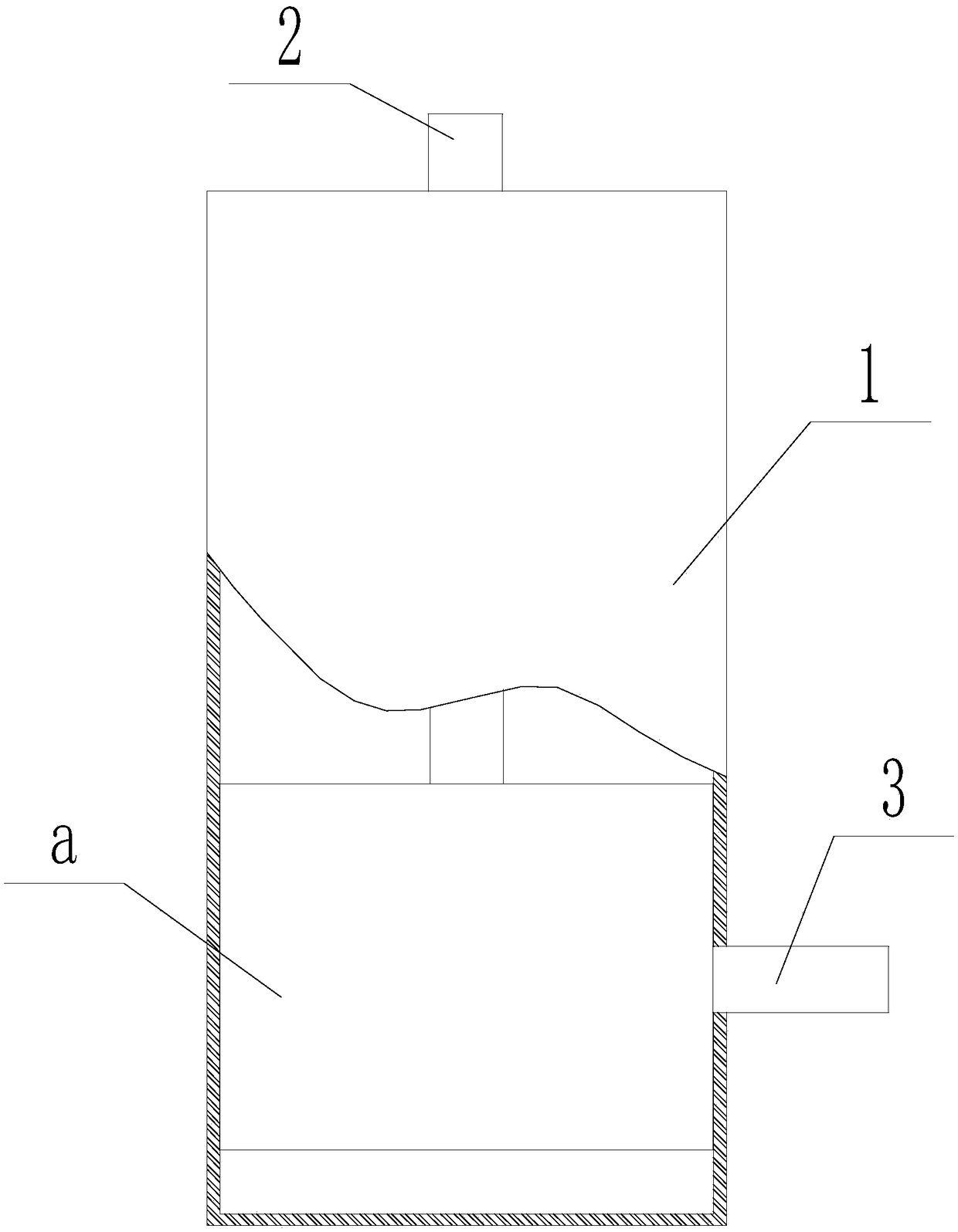
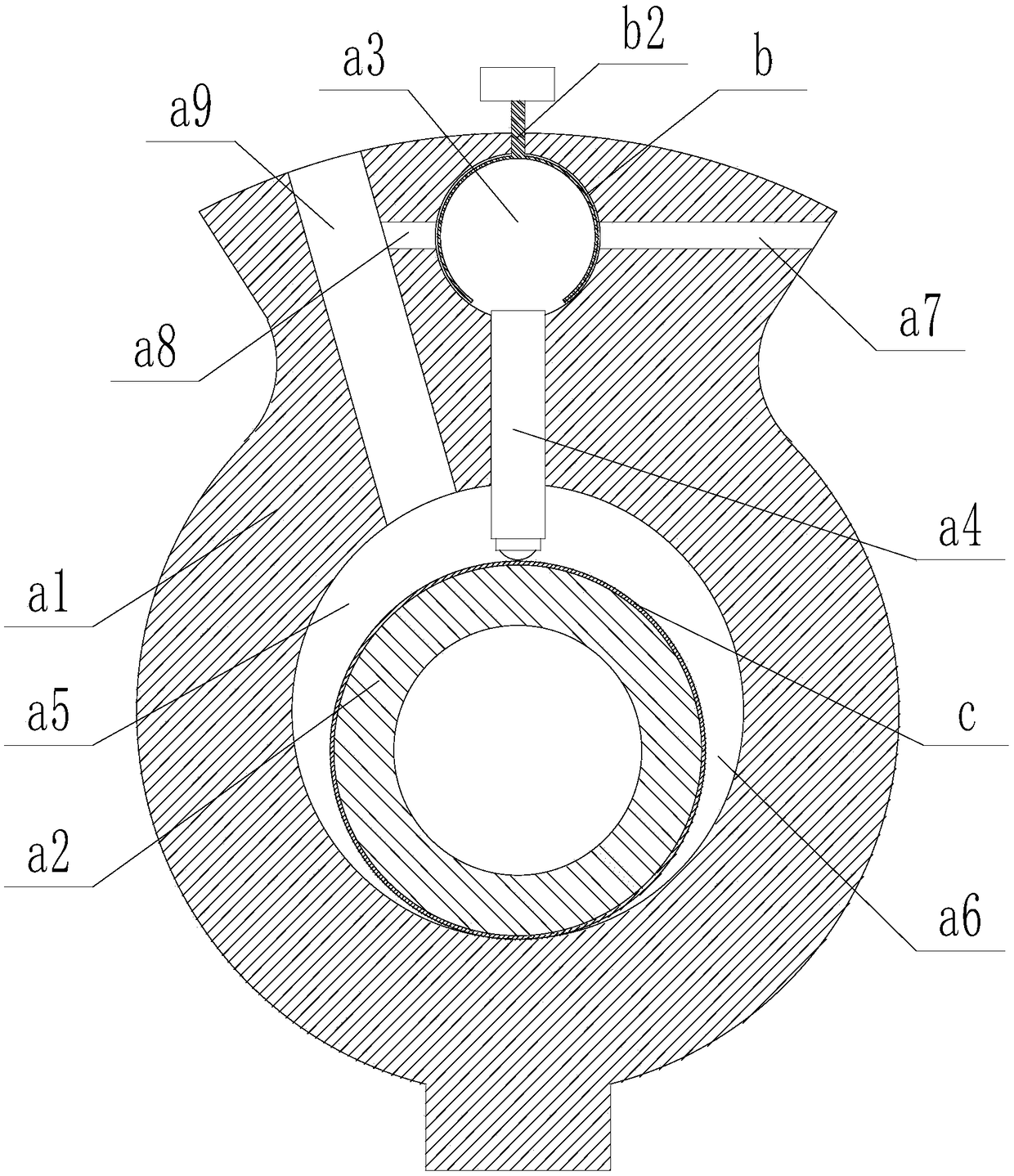
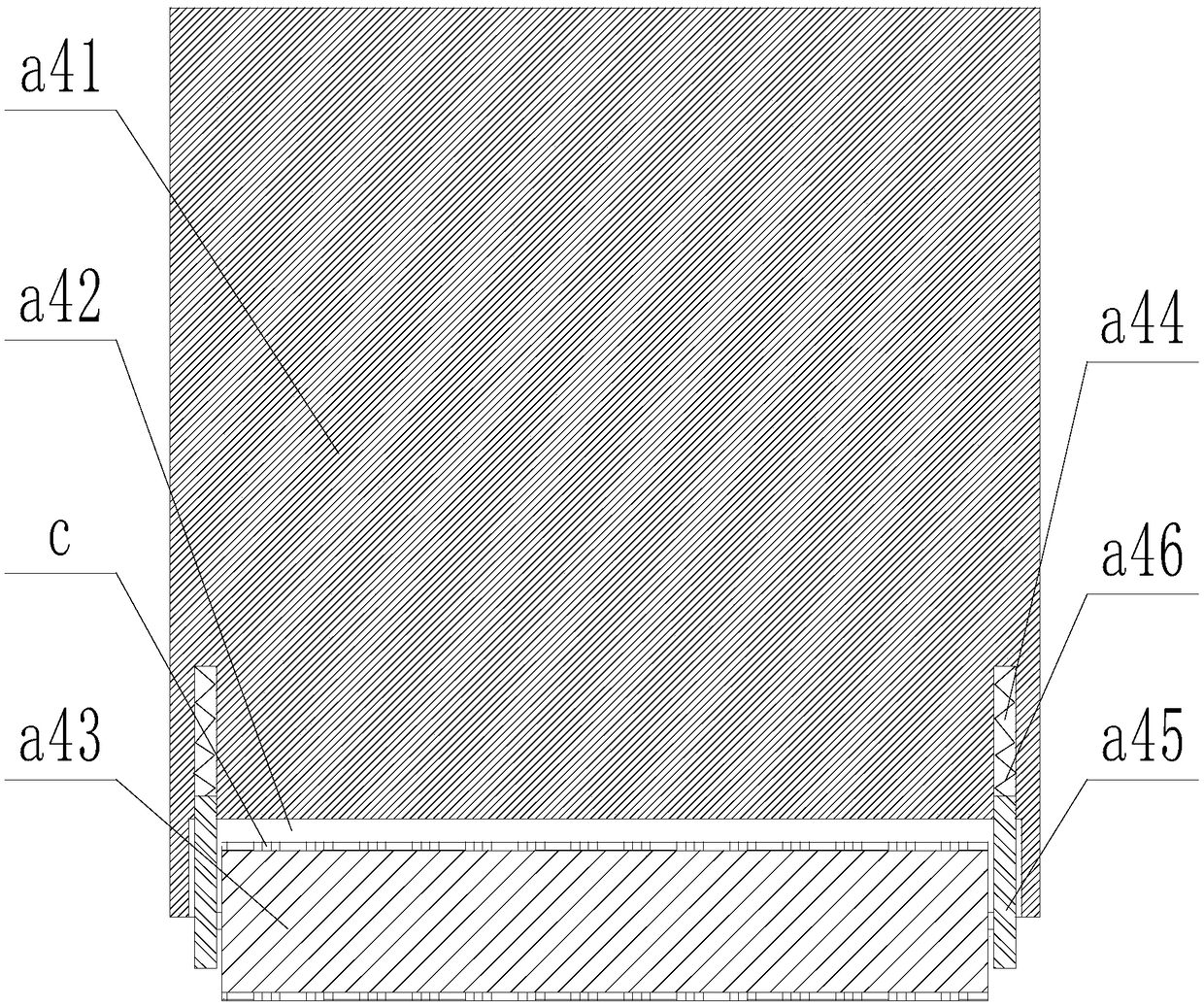
[0040] Such as Figure 1-5 As shown in , an air conditioner compressor with variable capacity includes a compressor casing 1, a refrigerant discharge pipe 2 is arranged on the top of the compressor casing 1, and a compression device a is arranged on the lower part of the compressor casing 1, The box wall of the compressor box 1 is provided with a refrigerant suction pipe 3, and the compression device a includes an annular cylinder a1 and an annular piston a2, and the annular piston a2 moves along the annular The inner wall of the cylinder a1 revolves so as to form a working chamber between the inner wall of the annular cylinder a1, the inner wall of the annular cylinder a1 is horizontally provided with a vane groove a3, and the isolation vane a4 is movable in the vane groove a3, The isolation blade a4 protrudes into the working chamber and abuts against the annular piston a2, and divides the working chamber into a suction chamber a5 and a compression chamber a6. The suction ch...

Embodiment 2

[0048] Such as Figure 1-5 As shown in , an air conditioner compressor with variable capacity includes a compressor casing 1, a refrigerant discharge pipe 2 is arranged on the top of the compressor casing 1, and a compression device a is arranged on the lower part of the compressor casing 1, The box wall of the compressor box 1 is provided with a refrigerant suction pipe 3, and the compression device a includes an annular cylinder a1 and an annular piston a2, and the annular piston a2 moves along the annular The inner wall of the cylinder a1 revolves so as to form a working chamber between the inner wall of the annular cylinder a1, the inner wall of the annular cylinder a1 is horizontally provided with a vane groove a3, and the isolation vane a4 is movable in the vane groove a3, The isolation blade a4 protrudes into the working chamber and abuts against the annular piston a2, and divides the working chamber into a suction chamber a5 and a compression chamber a6. The suction ch...


PUM


Abstract

The invention discloses a volume variable air conditioner compressor comprising a compressor box. The compressor box is provided with a refrigerant discharge pipe and a refrigerant suction pipe. A compression device is arranged on the lower portion of the compressor box and comprises an annular cylinder and an annular piston. The inner wall of the annular cylinder is provided with a blade groove horizontally. An isolation blade is movably arranged in the blade groove, protrudes into a work cavity and abuts against the annular piston. An energy-saving decompression part is arranged at the groove bottom of the blade groove. Through the energy-saving decompression part, communication or closing of the blade groove and the refrigerant discharge pipe as well as the refrigerant suction pipe canbe achieved correspondingly. Compared with the prior art, the volume variable air conditioner compressor has the advantage that the contact state of the isolation blade and the annular piston can be adjusted by adjusting pressure of the blade groove, wherein the surfaces of the isolation blade and the annular piston are covered with excellent-performance high-thermal-insulation abrasion-resistantcomposite films, the limitation of use within the medium and low temperature range is broken, the heat conductivity coefficient of the surface of a workpiece is lowered through a ceramic thermal insulation layer, and an Ni-P alloy coating is reinforced with electrostatic spinning zirconia nanofibers.

Description

technical field [0001] The invention relates to the field of compressors, in particular to an air conditioner compressor with variable capacity. Background technique [0002] As the core component of the air conditioning system, the compressor is often in the state of high temperature, high pressure and high speed operation, and the application of new environmentally friendly refrigerants in the compressor system and the direction of the compressor towards higher efficiency and higher load The development has further exacerbated the friction and wear of the key parts and components of the compressor. Automotive air-conditioning compressor components usually adopt lightweight design to effectively improve the operating efficiency of the whole machine. However, replacing the iron parts of the compressor with light alloys represented by aluminum alloys still faces serious friction, wear and corrosion problems, among which the friction and wear between the rotary vane aluminum ...

Claims


Application Information

Patent Timeline
Patent Type & Authority Applications(China)
IPC IPC(8): F04C18/356F04C29/00F04C29/02
CPCF04C18/3562F04C29/00F04C29/02F04C2230/91F04C2240/20F04C2240/80
Inventor 曹靖
Owner 江苏昊科汽车空调有限公司
Learn More