

Biological nitrogen and phosphorus removal process of sewage and matched device of V-shaped biological aerated filter pool
A biological aerated filter, denitrification and phosphorus removal technology, applied in water/sewage multi-stage treatment, water/sludge/sewage treatment, aerobic and anaerobic process treatment, etc. There are few problems, such as the influence of biofilm activity, to achieve the effect of good effect, superior effluent quality and long filtration cycle.
- Summary
- Abstract
- Description
- Claims
- Application Information
AI Technical Summary
Benefits of technology
Problems solved by technology
Method used
Image

Examples
Embodiment 1V
[0078] Embodiment 1V type biological aerated filter device
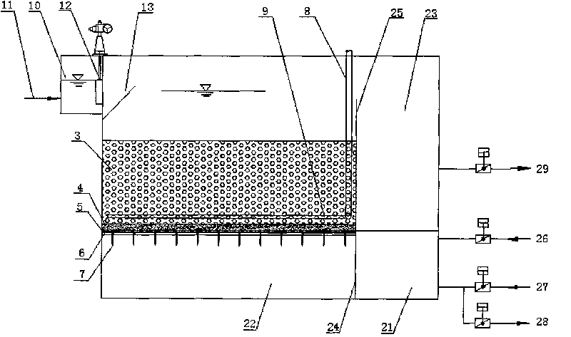
[0079] figure 1 It is a schematic diagram of the longitudinal section structure of the V-type biological aerated filter of the present invention. As can be seen from the figure, the upper part of the V-type filter is provided with a water inlet distribution channel 10, and the lower part of the water inlet distribution channel 10 is provided with a water inlet pipe 11. A water inlet gate 12 is provided at the joint between the water distribution channel 10 and the filter tank, and the water intake is controlled by the water inlet gate 12 .
[0080] Such as figure 1 As shown, the lower part of the V-shaped filter is provided with an air-water combined backwashing device, and the air-water combined backwashing device includes a backwashing air-water distribution tank 21, an air-water distribution chamber 22, and a backwashing drainage tank 23; wherein, the air-water The distribution chamber 22 is located below the ...
Embodiment 2
[0083] Example 2 Sewage Treatment Plant Renovation Project of Tahe Branch of China Petroleum & Chemical Corporation
[0084] Project Overview:
[0085] Sinopec Tahe Branch is located in Kuqa County, Xinjiang Uygur Autonomous Region. With the strengthening of national water protection and water conservation law enforcement, and the increase of water price, water conservation and emission reduction has been officially listed as the work of enterprises. schedule. This project is based on the original process, at the end of the construction of a V-type biological aerated filter deep biochemical system, and the final effluent of the sewage treatment plant is raised from the petrochemical industry level 2 of the "Comprehensive Sewage Discharge Standard" (GB8978-96) to the petrochemical industry The first-level indicator is also the basis for later-stage standard-reaching sewage reuse projects. The project was put into operation in 2005.
[0086] The basic situation of the project...
PUM
| Property | Measurement | Unit |
|---|---|---|
| Particle size | aaaaa | aaaaa |
| Particle size | aaaaa | aaaaa |
Abstract
Description
Claims
Application Information