Traffic diverging system for roundabout

A roundabout and diversion system technology, applied in the field of traffic diversion system, can solve the problems of inconvenient travel for non-motorized vehicles and pedestrians, long project period, limited improvement space, etc., and achieve the improvement of traffic efficiency and safety factor, traffic capacity and safety The effect of increased coefficient and less demand for traffic police and on-duty personnel

Inactive Publication Date: 2010-06-16
UNIV OF ELECTRONICS SCI & TECH OF CHINA
View PDF0 Cites 30 Cited by
  • Summary
  • Abstract
  • Description
  • Claims
  • Application Information

AI Technical Summary

Problems solved by technology

[0004] Though above-mentioned method has alleviated traffic pressure to a certain extent, there are also many problems: (1), the method for adopting signal light is in order to take into account each traffic lane, makes vehicle waiting time longer and longer, wastes a lot of resources (passenger's time and vehicle fuel consumption), increasing unnecessary pollution during low-peak periods; (2), using the improved geometric design method is not only difficult to design and simulate, but also has large errors, and the improvement space is very limited, making it difficult to adapt to the current rapidly growing traffic demand; (3), the way to build a bridge occupies a large area, needs to invest a lot of manpower and material resources, and the project period is long. During the construction period, it will affect the traffic flow and the lives of surrounding residents, and it is impossible and unrealistic to build an overpass bridge; (4), Adopting the method of separating intersections will inevitably change the track of some highways, and the cost is too high; (5), except that there is the same problem as building bridges, the method of adopting the construction of underground passages is more technically difficult, and it is not convenient for non-motorized vehicles and Pedestrian travel, and there is a great potential safety hazard; (6), the existing traffic channelization design has a narrow practical range, a short validity period and relatively high upgrade costs, the actual traffic channelization effect is not good, and the intersection has not been solved. traffic jams and accidents
[0015] The use of signal light control and channelization design can solve complex intersection problems well, but the current channelization design is mainly used for the design of traffic points with small flow and special-shaped intersections at the edge of the city. For large-flow intersections There are few good designs and few studies; and the existing channelization design is difficult to meet the land area and building protection requirements of the city center

Method used


Image

  • Traffic diverging system for roundabout
  • Traffic diverging system for roundabout
  • Traffic diverging system for roundabout

Examples


Embodiment 1

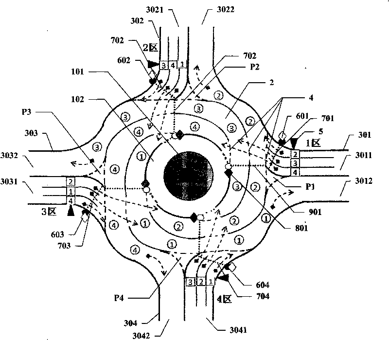
[0045] figure 1 It is a structural schematic diagram of a specific embodiment of the roundabout traffic diversion system of the present invention

[0046] Such as figure 1 As shown, in this implementation, the roundabout traffic diversion system includes a central roundabout 1, a ring road 2 around the center roundabout, and four main roads 301, 302, 303, 304 connected to the ring road 2, four main roads 301, 302 , 303, 304 correspond to zones 1, 2, 3, and 4, and each arterial road 301, 302, 303, 304 includes lanes 3011, 3021, 3031, 3041 for vehicles entering the intersection and lanes 3012, 3022, 3032 for leaving the intersection , 3042. In this implementation, the central roundabout 1 is composed of a circular parking lot 101 and a central plaza 102 .

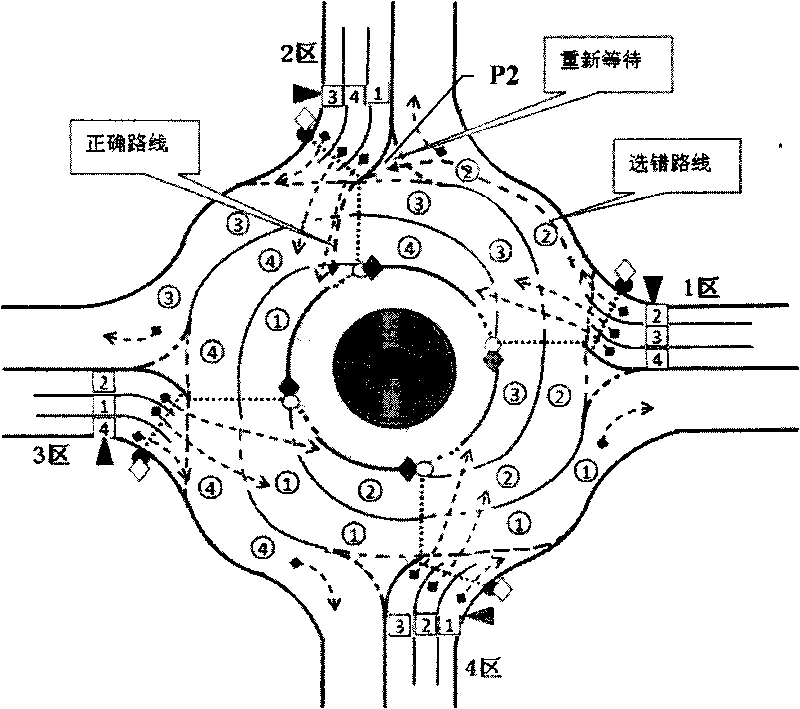
[0047] Ring road surface 2 includes four spiral lanes ①, ②, ③, ④. The four spiral lanes are divided into ①, ②, ③, and ④ starting from the central roundabout. Yes, then gradually extend outwards around the roundabout until t...

Embodiment 2

[0068] Figure 5 It is a structural schematic diagram of a specific embodiment of the roundabout traffic diversion system of the present invention.

[0069] The roundabout traffic diversion system of the present invention has a particularly obvious effect on large roundabouts with a large number of branch roads. The following takes the Arc de Triomphe Square in Paris as an example to illustrate.

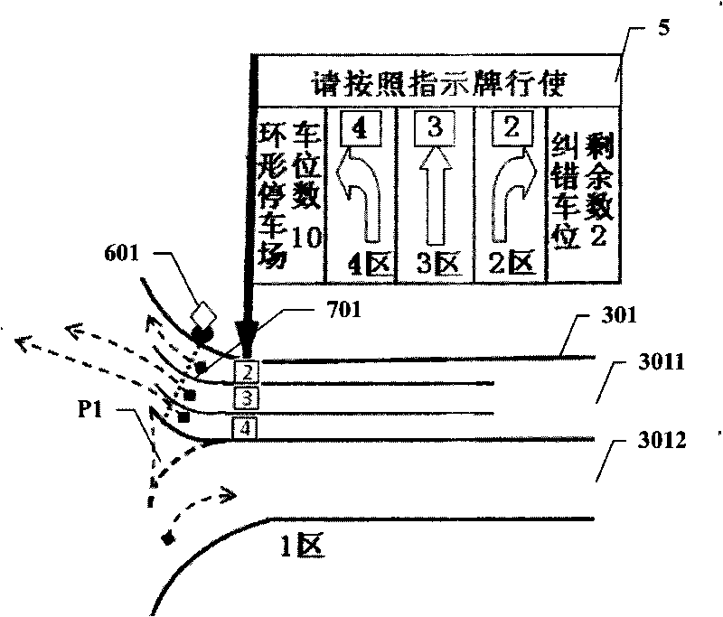
[0070] Such as Figure 4 As shown, there are twelve entrances and exits in the Arc de Triomphe Plaza, and the traffic collision problem at the roundabout is particularly serious, and congestion often occurs during peak hours. For this reason, four main roads 301, 302, 303, and 304 can be divided according to the traffic flow of each branch road, and can be divided into four areas such as 1, 2, 3, and 4 based on the principle of proximity, and each area includes a two-way main road. 1. The branch roads that only enter the roundabout and the branch roads that only exit the roundabout...


PUM


Abstract

The invention discloses a traffic diverging system for a roundabout. An annular road comprises four helical lanes, which start from a central roundabout opposite to the centre line of four arterial roads respectively, then, extend outwards gradually around the roundabout until surrounding three fourths of turn to the outermost layer of the annular road. The four helical lanes are connected with four lanes of the four arterial roads away from the roundabout. The helical lanes are dotted lines at the intersection with the arterial roads to permit vehicles to drive in. The arterial roads are divided into a left turn lane, a through lane, and a right turn lane, which are jointed with corresponding helical lanes respectively. A sign is arranged at the roundabout respectively for indicating the vehicles to turn left, go through or turn right to drive in the helical lanes. After driving in the roundabout, the vehicles enter the left turn lane, the through lane, or the right turn lane, namely a helical lane corresponding to a destination exit. The helical lanes can lead to each destination exit so as to avoid the conflict during leaving the roundabout. The vehicles only need to drive along the helical lanes, and drive away from the roundabout when reaching the destination exit.

Description

technical field [0001] The invention relates to a traffic diversion system, in particular to a traffic diversion system at a roundabout. Background technique [0002] In densely populated cities, traffic jams and traffic accidents have become bottlenecks that plague urban development, and most of the traffic jams and traffic accidents are at intersections, especially during rush hour, when intersections are blocked and deadlocked. Greatly reduced road capacity. [0003] At present, the usual practice is: (1), relieve the traffic pressure at the intersection by improving and optimizing the method of signal light control; (2), improve the traffic capacity by improving the length of the weaving section and the width of the road in the design of the roundabout; (3), through Geographically transfer the intersection to reduce the traffic pressure in a certain area; (4), build an overpass at the intersection or build a viaduct on the main road to avoid conflicts over the urban are...

Claims


Application Information

Patent Timeline
Patent Type & Authority Applications(China)
IPC IPC(8): E01C1/02
Inventor 王恒松龙兵黄琦张昌华李超李文江
Owner UNIV OF ELECTRONICS SCI & TECH OF CHINA
Why Eureka
Try Eureka