
Anchor Support Technology of Front Guide Beam of 900 Type Bridge Erecting Machine for Railway Passenger Dedicated Line

A technology of anchor frame and bridge erecting machine, which is applied in the direction of erecting/assembling bridges, bridges, bridge construction, etc. It can solve the problems of increasing the difficulty of pier construction, increasing material input, and affecting the erection of box girders, so as to shorten the period of girder erection, The effect of shortening the erection cycle and improving work efficiency

Active Publication Date: 2011-12-07
CHINA RAILWAY 16TH BUREAU GRP CO LTD +1
View PDF0 Cites 0 Cited by
  • Summary
  • Abstract
  • Description
  • Claims
  • Application Information

AI Technical Summary

Problems solved by technology

Such a cost is high, because the finish-rolled rebar is fixed on the bridge pier by pre-embedding, it cannot be taken out and reused after the simply supported box girder is erected, which increases the input of materials; secondly, it is difficult to recycle, and only Recycling the exposed materials of the pier body, and adopting the method of gas cutting, thus increasing the labor cost; thirdly, the difficulty of the construction of the pier is increased, and the labor cost is increased to ensure the accuracy of the position of the embedded parts when pouring the concrete of the pier. Because if the position cannot be guaranteed accurately during construction, it will seriously affect the erection of the box girder

Method used


Image

  • Anchor Support Technology of Front Guide Beam of 900 Type Bridge Erecting Machine for Railway Passenger Dedicated Line
  • Anchor Support Technology of Front Guide Beam of 900 Type Bridge Erecting Machine for Railway Passenger Dedicated Line
  • Anchor Support Technology of Front Guide Beam of 900 Type Bridge Erecting Machine for Railway Passenger Dedicated Line

Examples


Embodiment Construction

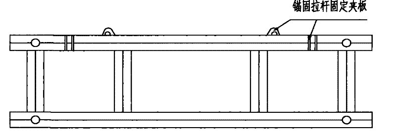
[0016] The anchor bracket of the front guide beam of the bridge erecting machine is processed into a box-shaped steel girder as a whole by butt welding of 200mm I-beam, on which 8 pieces of anchor rods processed by 20mm thick steel plate are welded to fix the splint. It is the anchor screw rod used to connect the anchor bracket with the prefabricated concrete simply supported box girder of the passenger dedicated line. The bolts lock the anchor bracket and the precast concrete simply supported box girder of the passenger dedicated line together. At the same time, weld the screw fixing splint on the rear end of the leading beam of the bridge erecting machine, and make it correspond to the position of the fixing splint on the anchor bracket. During implementation, the fixed splint on the leading beam of the bridge erecting machine is connected with the anchor bracket by using a two-way telescopic lead screw available on the market.

[0017] The technical invention has been veri...


PUM


Abstract

The present invention is an anchoring bracket for a leading beam when a 900-ton bridge-erecting machine passes through a hole in a high-speed railway for passenger dedicated lines. Anchor holes are reserved at the hoisting holes of the precast concrete simply supported beams for passenger dedicated lines. The auxiliary guide beam in front of the bridge erecting machine is connected with the prefabricated concrete simply supported beam of the passenger dedicated line by using a two-way telescopic screw rod, so as to achieve the function of fixing the outrigger of the bridge erecting machine, so as to realize the safety of the bridge erecting machine in the working state of passing through the hole sex and stability. It has a simple structure and low cost; it has great practicability, and it can be used in various types of bridge erecting machines with only a small change in the size of the screw splint; it is safe and reliable in operation and has high sensitivity; the structure can be reused to reduce repeated waste of materials , reduce the construction difficulty of the leading process, and can effectively save project funds.

Description

technical field [0001] The technical invention belongs to the construction field of high-speed railway passenger dedicated line, and solves the temporary anchoring device when the 900-ton bridge erecting machine passes through the hole. Background technique [0002] Now my country's high-speed railway is under rapid construction. In the construction of high-speed railway, viaducts are usually used to solve various problems restricting the line. During the bridge erection process, due to the large size of the prefabricated concrete simply supported box girder of the passenger dedicated line (the beam length is 32.6m) and the heavy tonnage (the mass of the single-hole box girder reaches 900t), only professional bridge erection machines can be used for construction. The main body of the bridge erecting machine currently in use is divided into two parts: one is the main beam part, which is the main body of the bridge erecting frame beam when it is working; the other is the front...

Claims


Application Information

Patent Timeline
Patent Type & Authority Patents(China)
IPC IPC(8): E01D21/00
Inventor 公彦良李征陈胜旺
Owner CHINA RAILWAY 16TH BUREAU GRP CO LTD
Learn More